M2540-92000-01 A M2540 Ultrasound System Field Service Manual Page 8
General Information: System Description
The optional Physio module installs in one of the PC’s front drive bays. An optional
magneto-optical disk (MOD) drive can also be installed in one of the drive bays. The VCR option
includes three boards that reside in the PC’s PCI slots, and a VCR that mounts on the cart.
See “Internal PC” on page 39 for more detailed information about the PC and its components.
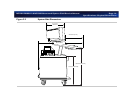
System Monitor
The monitor at the top of the cart is a 15-inch color display mounted on a “twivel” assembly.
The twivel allows tilt and swivel positioning of the display for ease of viewing.
e-box
The e-box houses the scanner circuit boards, and is accessible by opening the door at the right
rear of the cart.
There are several circuit boards in the e-box:
• Two transmit and receive (TR) boards
• A beam processor/acoustic processor (BPAP) board
• A demodulator board
• The system motherboard
• The distribution board
System Control
Panel
The system control panel at the top front of the cart is a replaceable, self-contained module. See
“Replacing the System Control Panel” on page 159. The panel interfaces with the imaging system
through a USB cable that connects to the internal PC. Power for the trackball is provided via the
USB cable. All the other control-panel functions are powered by a cable from the system power
supply.
The system control panel contains a backlit alphanumeric keyboard, slide controls, rotary
controls, hard-coded and software-driven keys, and a trackball.


