M2540-92000-01 A M2540 Ultrasound System Field Service Manual Page 98
Performance Tests: Electrical Safety Tests
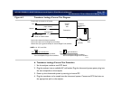
4. Connect ECG leads to the ultrasound system, but do not connect the ECG leads to the
analyzer yet.
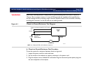
5. In normal polarity, perform a lead isolation test. Record the reading in microamperes. This
reading is the correction factor used in step 7.
6. Connect all ECG leads to the appropriate jacks on the analyzer and perform a lead isolation
test. Record the reading in microamperes.
7. Subtract the step 5 correction factor from the step 6 reading to get an accurate isolation
leakage measurement. Record this value. Check that the value is within the limit specified in
Figure 6-4 on page 97.
NOTE Some analyzers do not require subtracting the correction factor from the lead isolation
reading. Refer to the analyzer’s documentation for more information.
Tr an sd uc er
Tests
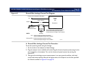
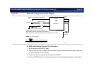
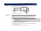
Two electrical leakage current tests for transducers are described in this section. To insure
patient safety, it is very important to verify the integrity of the insulating layers of all transducers.
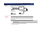
When performing the safety tests, saline solution in a container is used as a conductive medium
(see Figure 4-4 on page 53). The solution penetrates any cracks or holes in the transducer
insulation and provides an electrical path between the submerged lead wire and the inner
transducer shield.
“Transducer Safety Testing: Test Setup and Theory” on page 52 includes supporting information
about the transducer tests. This is supplemental information, and is not required to complete the
tests.
NOTE Before proceeding with any transducer test, thoroughly inspect the transducer. If the
transducer is a TEE, check that its steering controls are working properly.


