M2540-92000-01 A M2540 Ultrasound System Field Service Manual Page 44
Theory of Operation: System Motherboard
Primary
Functions
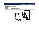
The module’s primary functions are as follows:
• Process electrocardiogram (ECG) signals from patient electrodes and deliver the data to the
M2540A’s PC
• Send a detected R-wave trigger to the APIO board for frame triggering in various scanning
modes
• Provide gain control for ECG waveforms
Connectors
The Physio module has two connectors on its front panel:
• The ECG-input connector is a round, 12-pin connector that is isolated from chassis ground.
• A ¼-inch phone plug jack accepts auxiliary input and has both signal and shield grounds.
System
Motherboard
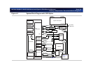
This board connects all data paths between the TR boards, the BPAP board, and the distribution
board. It is also the distribution point for DC power and ground to all boards (the BPAP board
and distribution board also receive power directly from the system power supply.). It also sends
filtered high voltage to the TR boards.
Distribution
Board and
Connector
Modules
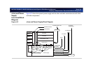
The distribution board passes transducer signal inputs to the imaging system. The system power
supply provides high voltage directly to the distribution board to fire transducers.
Signals that pass through this board include
• Transducer identification signals from the BPAP board to and from the transducer
• Transmit and receive signals from the TR boards to the active transducer
• TEE motor-control and temperature-sense signals from the BPAP to and from the TEE trans-
ducer


