M2540-92000-01 A M2540 Ultrasound System Field Service Manual Page 93
Performance Tests: Electrical Safety Tests
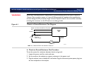
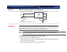
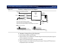
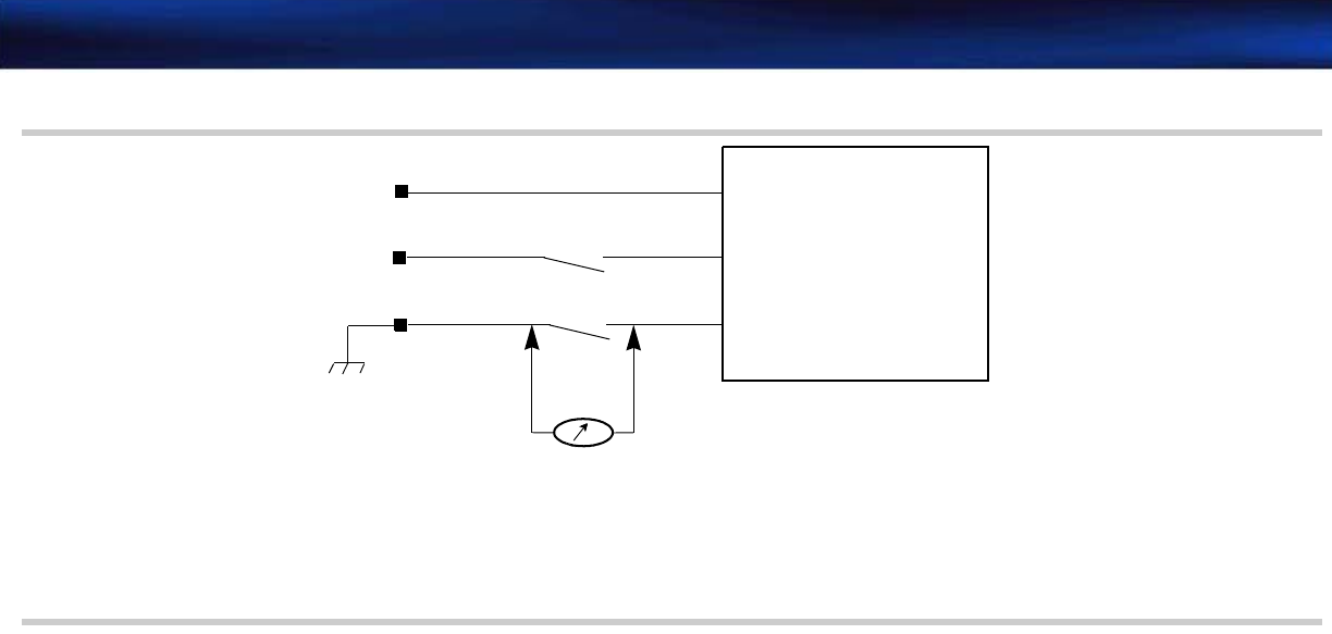
Figure 6-2 Ground Wire Leakage Current Test Diagram
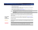
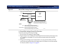
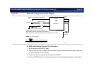
➤ Ground Wire Leakage Current Test Procedure
To test the system’s ground wiring for leakage:
1. Set the mode on the analyzer to detect leakage.
2. Plug the analyzer into an available wall outlet. Plug the ultrasound system power plug into the
test receptacle on the analyzer. Turn on the ultrasound system’s power by starting the
internal PC.
3. Take ground wire leakage current measurements in an open ground condition, with both
normal and reverse polarity. Record the highest value, and compare it to the limit specified
for Normal condition in Figure 6-2 on page 93.
Hot -
AC micro-
ammeter
Powered on
UL:
I
= 300 microamperes Normal condition,
CSA and IEC:
I
= 500 microamperes Normal condition,
Neutral -
LIMITS:
Ground wire
Green or
Green/Yellow
1000 microamperes Single Fault condition
1000 microamperes Single Fault condition
7ASW025
System
under
test
Power cord connected to AC power.
I
(current)
(open neutral)
(open ground)
Ground wire open for Normal condition
Ground wire and neutral wire open
simultaneously for Single Fault condition


