


12 Verification and Performance Tests
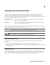
Measurement Techniques
Setup for Most Tests
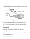
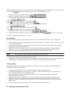
Most tests are performed at the rear terminals as shown in the following figure. Measure the dc voltage directly at the + S
and - S terminals. Set the connector sense switch for local sensing and use adequate wire gauge for load leads as described
in Chapter 2 of the Power Module User’s Guide.
Figure 2-1. Performance Test Setup
Many of the test procedures require the use of a variable load capable of dissipating the required power (see Table 1-1). If a
variable resistor is used, switches must be used to connect, disconnect, and short the load resistor. For most tests, an
electronic load can be used. The electronic load is considerably easier to use than load resistors but some may not be fast
enough to test transient recovery time and may be too noisy for the noise (PARD) tests. Fixed load resistors may be used in
place of a variable load, with minor changes to the test procedures in this chapter. Also, if computer controlled test setups
are used, the relatively slow (compared to computers and system voltmeters) settling time and slew rates of the power
module may have to be taken into account. WAIT statements can be used in the test program if the test system is faster than
the module.
Current-Monitoring Resistor
To eliminate output current measurement error caused by voltage drops in the leads and connections, connect the current
monitoring resistor between the output and the load as a four-terminal device (see R
M
in Figure 2-1). Connect the current
monitoring leads inside the load lead connections directly at the monitoring points on the resistor element.
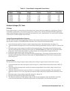
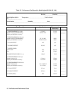
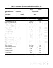
Programming
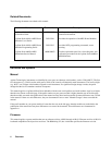
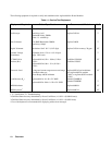
Table 2-1 lists the programming and current values for each module. You may program the module from the MPS Keyboard
or from a GPIB controller when performing the tests. The test procedures are written assuming that you know how to do
either or both. Complete instructions for remote and local programming are given in the module Power Module
Programming Guide and Power Module User’s Guide.