


Diagrams 83
6
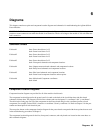
Diagrams
This chapter contains test point and component location diagrams and schematics for troubleshooting the Agilent 6610xA
Power Modules.
SHOCK HAZARD Hazardous voltages are present throughout the Power and Bias board assemblies. Ac line voltage is
present on some connectors even when the module is not turned on. The dc rail voltage to the module is 310 volts when the
unit is turned on.
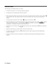
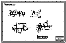
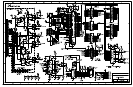
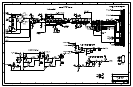
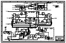
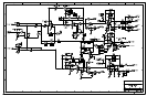
Schematic Sheets
Foldout #1 front--Power board sheet 1 of 5
back--Power board sheet 2 of 5
Foldout #2 front--Power board sheet 3 of 5
back--Power board sheet 4 of 5
Foldout #3 front--Power board sheet 5 of 5
back--Front panel schematic and component locations
Foldout #4 front--Output connector board schematic and component locations
back--Relay board schematic and component locations
Foldout #5 front--Bias board schematic and component locations
back--Power board component locations and test points
Foldout #6 front--Main board Component coordinates
back--blank
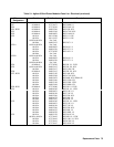
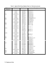
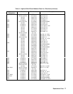
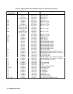
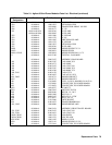
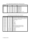
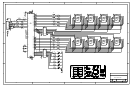
Component Location Diagrams
Component location diagrams are provided for all of the module circuit boards.
The component location diagram for the power board is located on the back of the last foldout sheet (the bias board
schematic) foldout sheet. The diagram is divided into columns and rows designated "x coordinates" and "y coordinates".
The table on the facing page lists all of the components on the Power board and gives the coordinate location of each
component. For example, resistor R201 is located at x coordinate 3.9 and y coordinate 1.4. Refer to Chapter 5 for the part
number and description of each electrical part.
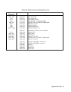
The test points shown on the component location diagram for the power board correspond with the test points that are used
in the troubleshooting procedures of Chapter 3.
The component location diagrams for the bias, front panel, connector, and relay boards are located on the same sheets as
their schematic diagrams.