


Troubleshooting 25
3
Troubleshooting
This chapter provides troubleshooting and repair information for the Agilent 6610xA Power Modules. Before attempting to
troubleshoot the modules, ensure that the problem is not with an external circuit or application, the mainframe, the GPIB
controller, the application program, or the input power line.
SHOCK HAZARD Most of the troubleshooting procedures given in this chapter are performed with power
applied and protective covers removed. Such maintenance should be performed only by trained
service personnel who are aware of the hazards (for example, tire and electrical shock).
Hazardous voltages are present throughout the Power and Bias board assemblies. Ac line voltage is present
on some connectors even when the module is not turned on. The dc rail voltage to the module is 310 volts
when the unit is turned on.
Troubleshooting Sequence
1. Verify that the module is at fault.
2. Use the flowcharts to locate the functional block at fault.
3. Troubleshoot the functional block per flowchart instructions.
Selftest routines built into firmware are provided to help isolate a problem to a particular circuit on the board. Once a
problem has been isolated to a circuit, suggestions are given in the appropriate flowchart as to what component may be at
fault.
This instrument uses components that can be damaged or suffer serious performance degradation as a
result of ESD (electrostatic discharge). Observe the standard anti-static precautions discussed in
Chapter 1 to avoid damage to components.
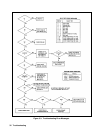
Accessing the Flowcharts
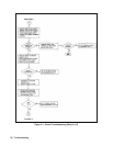
The following troubleshooting flowcharts are provided to help you identify and isolate a problem to a specific circuit. Once
a problem has been narrowed down, suggestions are provided as to the components that may be responsible for the problem.
Refer to the schematic diagrams for detailed information on circuit wiring and component function.
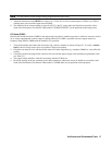
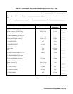
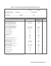
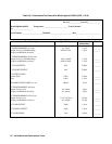
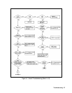
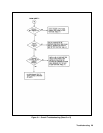
þ Figure 3-1 - Overall Troubleshooting
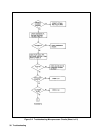
þ Figure 3-2 - Troubleshooting Microprocessor Circuits
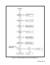
þ Figure 3-3 - Troubleshooting Error Messages
þ Figure 3-4 - Troubleshooting Overvoltage at Turn-on