


Verification and Performance Tests 13
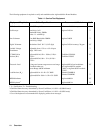
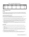
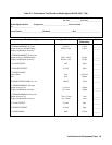
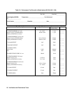
Table 2-1. Power Module Voltage and Current Values
Agilent
Model
Full-Scale
Voltage
Max. Prog.
Voltage
Full-Scale
Current
Max. Prog.
Current
Max. Prog.
Overvoltage
66101A 8V 8.190V 16A 16.380A 10V
66102A 20V 20.475V 7.5A 7.678A 24V
66103A 35V 35.831V 4.5A 4.607A 42V
66104A 60V 61.425V 2.5A 2.559A 72V
66105A 120V 122.85V 1.25A 1.280A 144V
66106A 200V 204.75V 0.75A 0.768A 240V
Constant Voltage (CV) Tests
CV Setup
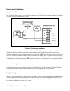
If more than one meter or a meter and an oscilloscope are used, connect each to the terminals by a separate pair of leads to
avoid mutual coupling effects. For constant voltage dc tests, connect only to + S and - S because the module regulates the
output voltage that appears between those terminals, not between the + and - output terminals. Use coaxial cable or shielded
2-wire cable to avoid noise pickup on the test leads.
Voltage Programming/Readback Accuracy
This test verifies that the voltage programming, readback, and front panel display functions are within specifications. Note
that the values read back over the GPIB should be identical to those displayed on the keyboard display.
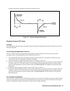
1. Turn off the power module and connect a digital voltmeter between the + S and--S terminals (see Figure 2-1).
2. Turn on the module and program it for zero volts and the maximum programmable current (see Table 2-1) with the load
off.
3. Record the output voltage readings on the DVM and the keyboard display. The readings should be within the limits
specified in the Performance Test Record Tables under CV PROGRAMMING @ 0 VOLTS, for the particular model
being tested. The CV annunciator should be on and the output current reading should be approximately zero.
4. Program the output voltage to full scale (see Table 2-1).
5. Record the output voltage readings on the DVM and the keyboard display. The readings should be within the limits
specified in the Performance Test Record Tables under CV PROGRAMMING @ FULL SCALE, for the particular
model being tested.
CV Load Effect
This test measures the change in output voltage resulting from a change in output current from full-load to no-load.
1. Turn off the module and connect the output as shown in Figure 2-1 with the DVM connected between the + S and - S
terminals.
2. Turn on the module and program the current to the maximum programmable value and the voltage to the full-scale
value (see Table 2-1).
3. Adjust the load for the full-scale current (see Table 2-1) as indicated on the keyboard display. The front panel CV
annunciator must be on. If it is not, adjust the load so that the output current drops slightly until the annunciator comes
on.
4. Record the output voltage reading on the DVM connected to + S and - S.
5. Open the load and again record the DVM voltage reading.
6. The difference between the DVM readings in steps (4) and (5) is the load effect voltage and should not exceed the
value listed in the Performance Test Record Tables under CV LOAD EFFECT, for the model being tested.