


14 Verification and Performance Tests
CV Source Effect
This test measures the change in output voltage that results from a change in ac line voltage from the minimum to maximum
value within the line voltage specifications.
1. Turn off the module and connect the ac power line through a variable-voltage transformer.
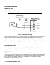
2. Connect the output as shown in Figure 2-1 with the DVM connected between the + S and - S terminals. Set the
transformer to nominal line voltage (either 115Vac or 230Vac).
3. Turn on the module and program the current to the maximum programmable value and the output voltage to the
full-scale value (see Table 2-1).
4. Adjust the load for the full-scale current value (see Table 2-1) as indicated on the keyboard display. The front panel CV
annunciator must be on. If it is not, adjust the load so that the output current drops slightly until the annunciator comes
on.
5. Adjust the transformer to the LOW line voltage (e.g., 87Vac for a 115Vac nominal input, or 174Vac for a 230Vac
nominal input).
6. Record the output voltage reading on the DVM.
7. Adjust the transformer to the HIGH line voltage (e.g., 132Vac for a 115Vac nominal input, or 250Vac for a 230Vac
nominal input).
8. Record the output voltage reading on the DVM.
9. The difference between the DVM readings in steps (6) and (8) is the source effect voltage and should not exceed the
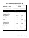
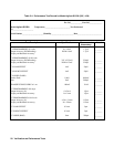
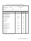
value listed in the Performance Test Record Tables under CV SOURCE EFFECT, for the model being tested.
CV Noise (PARD)
Periodic and random deviations (PARD) in the output (ripple and noise) combine to produce a residual ac voltage
superimposed on the dc output voltage. This test measures CV PARD, specified as the rms or peak-to-peak output voltage
over the frequency range of 20Hz to 20MHz.
1. Turn off the module and connect the output as shown in Figure 2-1 to an oscilloscope (ac coupled) between the + and--
terminals. Set the oscilloscope’s bandwidth limit to 20MHz (30MHz on the Agilent 54504A) and use an RF tip on the
oscilloscope probe.
2. Turn on the module and program the current to the maximum programmable value and the output voltage to the
full-scale value (see Table 2-1).
3. Adjust the load for the full-scale current value (see Table 2-1) as indicated on the keyboard display.
4. The waveform on the oscilloscope should not exceed the peak-to-peak limits in the Performance Test Record Tables
under CV NOISE (PARD), for the model being tested.
5. Disconnect the oscilloscope and connect an ac rms voltmeter in its place. The rms voltage reading should not exceed
the rms limits in the Performance Test Record Tables under CV NOISE (PARD) for the model being tested.
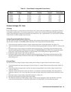
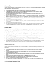
Transient Recovery Time
This test measures the time for the output voltage to recover to within the specified value following a 10% change in the
load current.
1. Turn off the module and connect the output as shown in Figure 2-1 with the oscilloscope across the + S and -S
terminals.
2. Turn on the module and program the output voltage to the full-scale value and the current to the maximum
programmable value (see Table 2-1).
3. Set the load to the Constant Current mode and program the load current to 90% of the power module full-scale rated
current.
4. Set the electronic load’s transient generator frequency to 100Hz and its duty cycle to 50%.
5. Program the load’s transient level to the module’s full-scale current value and turn the transient on.
6. Adjust the oscilloscope for a waveform similar to that in Figure 2-2.
7. The output voltage should return to within 100mV of the nominal value in less than 1ms. Check both loading and