


64 Thoery Of Operation
Pulse-Width Modulator, FETS, and Isolation Transformer
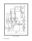
The pulse-width modulator controls the FETS. The FETS are arranged in an "H" bridge configuration with the + and - dc
rail at the top and bottom of the H. The 4 FETS are located on each leg of the "H", and the isolation transformer is located
on the horizontal bar of the H. The FETS located diagonally across from each other are alternately turned on and off (Q201
and Q204 are turned on, then off; followed by Q202 and Q203 being turned on, then off).
In this way current flows from the + dc rail through the primary of T201 to the - dc rail. When Q201 and Q204 are on,
current flows through the primary of T201 in one direction. When Q202 and Q203 are on, current flows through the primary
of T201 in the opposite direction. This generates the positive and negative pulses on the secondary winding of T201. The
output of T201 is then rectified and filtered to produce the dc output.
T202, located in series with T201, is part of the peak current limit circuit, which limits the amount of current that can flow
through the FETs. This protects the internal and external circuits from excessive currents that may result when the output of
the module is shorted.
Downprogrammer Circuit
The downprogrammer circuit internally draws current through the output rectifier and filter to keep the FET circuits turned
on when the module is programmed to a low or zero output. The maximum current that flows through the downprogrammer
is 10% of the total output current .
The downprogrammer circuit monitors the current at the output of the module and turns off when the output current reaches
1/2 of its full-scale rating.
Additionally, when voltage is programmed to a low value or programmed off, the downprogrammer helps to pull down the
output of the supply to speed up downprogramming time.
Readback Multiplexer
The readback multiplexer and the readback A to D are used to read back information from the module during normal
operation and during selftest. The microprocessor selects an input on the readback multiplexer and reads back data on that
input. The following signals comprise the inputs to the multiplexer:
IMON
VMON
+12V reference
+5V reference
temperature reference
power turn-on switch setting
CV DAC output
CC DAC output
The multiplexer inputs are between 2.5 volts and -2.5 volts, which is the voltage range of the 16-bit readback A to D
converter. The IMON and VMON signals are in the range of 0 to 2 volts, which represents the 0 to full-scale output of the
supply. The readback A to D converter converts the analog signal from the multiplexer to a digital signal, which is returned
to the microprocessor. The microprocessor in turn sends the corrected (calibrated) data to the display.