


58 Troubleshooting
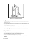
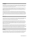
Figure 3-15. Front Panel Assembly Locking Tabs
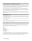
Installing the Power Board
1. Insert the tabs along the bottom edge of the board in the corresponding slots on the bottom of the chassis and carefully
install the board in the chassis.
2. Use the T10 driver and insert the four screws (two toward the back and two near the center) that attach the Power board
to the chassis.
3. Connect the front panel cable into the J3 connector, the bias board cables into the J301 and J302 connectors, and the
fan cable into the J102 connector on the Power board.
4. Insert the front panel cable and the bias board cables into the appropriate cable cutout on the fan bracket.
5. To prevent the cover from pinching the cables, route the front panel cable, the longer bias board cable, and the fan
cable between T201 and L201.
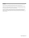
Installing the Bias Board
1. Carefully install the Bias board so that T401 is positioned up against the fan bracket.
2. Use the T10 driver and insert the two screws at the front that attach the Bias board to the chassis.
3. Connect the bias board cables into the J401 and J402 connectors on the Bias board.
4. Insert the bias board cables into the appropriate cable cutout on the fan bracket. Route the longer bias cable in between
T201 and L201.