


Troubleshooting 59
Installing the Front Panel Board and Front Panel Assembly
1. Install the front panel, the front panel board, and the latch assembly in one of the front assembly halves.
2. Make sure that the front panel board is positioned in the slot closest to the front panel.
3. Carefully snap the other half of the front panel assembly together.
4. Insert the tab on the top of the front panel assembly in the corresponding notch on the chassis and position the front
panel assembly into the chassis. The two tabs on the side of the assembly should be positioned in the corresponding
notches on the side of the chassis.
5. Connect the front panel cable into the J3 connector on the Power board. Route the cable through the cutout on the fan
bracket and in between T201 and L201.
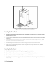
Installing the Fan
1. Position the fan up against the fan bracket.
Make sure that the arrow on the fan is pointing to the BACK of the module. The airflow must be from
the front of the module to the back of the module.
2. Use the T10 driver and 7mm nut driver and insert the two screws and nuts that connect the fan to the fan bracket. Place
the locking nuts against the fan bracket.
3. Connect the fan cable into the J102 connector on the Power board. Route the cable in between T201 and L201.
Installing the Cover
1. Position the cover over the chassis so that the screw holes and the notches on the front panel assembly notches line up
with the corresponding openings in the cover. Make sure that no cables are being pinched by the cover.
2. Use the T10 driver and insert the seven screws that connect the chassis cover to the chassis