56 Troubleshooting
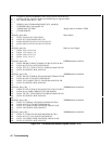
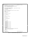
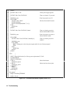
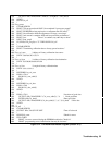
2010 STOP
2020 END IF
2030 !
2040 PRINT "Operation complete. Program stopped."
2050 STOP
2060 !
2070 Ps_error: ! Error handling subroutine
2080 OUTPUT @Ps;"SYST:ERR?" ! Check for errors
2090 ENTER @Ps;Err
2100 RETURN
2110 !
2120 END
Figure 3-14. EEPROM Initialization Program (Sheet 5 of 5)
Disassembly Procedures
This section describes how to disassemble and reassemble the Agilent 6610xA Power Modules. Refer to Chapter 5 for the
component descriptions. Refer to Chapter 1 for the tools required to disassemble and reassemble the unit.
Most of the attaching hardware is metric. Using the wrong fasteners will damage threaded inserts.
Observe all standard anti-static procedures when removing the pc boards from the chassis (see
Chapter 1).
Removing the Module and Module Connector
Before you can disassemble the module, you must first remove the power modules from the mainframe.
1. Use the slot-head screwdriver and release the pull tab at the front of each module.
2. Pull the power module out of the mainframe.
3. To remove the module connector, use the Pozi driver and disconnect the module connectors from the back of the
mainframe.
Removing the Cover
1. Use the T10 driver and remove the seven screws that connect the chassis cover to the chassis.
2. Lift the cover off.
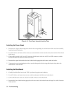
Removing the Fan
1. Carefully unplug the fan cable from the J102 connector on the Power board.
2. Use the T10 driver and 7mm nut driver and remove the two screws that connect the fan to the fan bracket.
3. Remove the fan.


