


48 Troubleshooting
Test Points
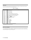
The following test points are referenced in the troubleshooting flowcharts. Refer to the component locations diagram in
Chapter 6 for the actual location of the test points on the pc board.
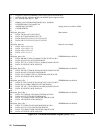
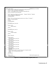
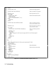
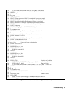
Table 3-1. Test Points
Test Point Description
TP 0
Output circuit common (located on inboard side of R303)
TP 1
+5V (4.8 to 5.2 volts)
TP 2
+12V (11.4 to 12.6 volts)
TP 3
+7V (6.7 to 7.3 volts)
TP 4
+2.5V (2.4 to 2.6 volts)
TP 5
-12V (-11.4 to -12.6 volts)
TP 6
+15V (14.25 to 15.75 volts, referenced to the-rail)
l
TP 7
+5V (4.75 to 5.25 volts, referenced to frame common)
TP 8
+24V (24.3 to 27.3 volts, referenced to frame common)
TP 9
+28V (unregulated, referenced to frame common)
TP 10
Frame common
\
/
F
TP 11
PCLR* (goes low for 175ms at turn-on)
TP 12
6MHz (microprocessor clock out)
TP 13
3MHz (A/D clock in)
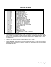
TP 14
+ output
TP 15
-output
TP 16
0 to-6V (CVPROG)
TP 17
0 to-6V (CCPROG)
TP 18
0 to 2V (A/D INPUT)
TP 19
0 to 2V (VMON)
TP 20
0 to 2V (IMON)
TP 21
0 to 4V (OVREF)
TP 22
-3.4 to -4V (OR GATE, output dependent)
1 Test Equipment must be isolated from ground.
Built-In Test Functions
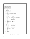
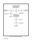
To aid in troubleshooting, the module configuration switch (S3) can be set to run various test routines as described in the
Overall Troubleshooting flowchart. To start the test, set all switches to 0 (down) and turn on ac power. Then set the switch
to perform the selected test as shown in the following table.