


Troubleshooting 49
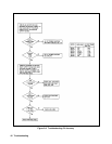
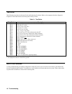
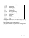
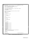
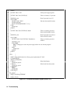
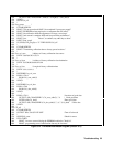
Table 3-2. S3 Test Settings
S3 Setting Test Description
8 7 6 5 4 3 2 1
0 0 0 0 0 0 0 0 Start with blank front panel
0 0 0 1 0 0 0 0 Front panel with all segments on
0 0 0 0 0 0 0 1 VDAC minimum (TP16 = 0V)
0 0 0 1 0 0 0 1 VDAC maximum (TP16 = -VREF)
0 0 0 0 0 0 1 0 IDAC minimum (TP17 = 0V)
0 0 0 1 0 0 1 0 IDAC maximum (TP17 = -VREF)
0 0 0 0 0 0 1 1 OVPDAC minimum (TP21 = 0V)
0 0 0 1 0 0 1 1 OVPDAC maximum (TP21 = 4V)
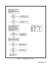
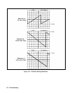
0 0 0 0 0 1 0 0 VDAC ramp slow (TP16, see waveform B)
0 0 0 1 0 1 0 0 VDAC ramp fast (TP16, see waveform C)
0 0 0 0 0 1 0 1 IDAC ramp slow (TP17, see waveform B)
0 0 0 1 0 1 0 1 IDAC ramp fast (TP17, see waveform C)
0 0 0 0 0 1 1 0 OVPDAC ramp (TP21, see waveform A)
0 0 0 1 0 1 1 1 MUX/AD (Toggle S3 switch 5 to select input)
0 0 0 0 1 0 0 0 SRST* and OVPRST$ pulse
0 0 0 0 1 0 0 1 PWMENhigh
0 0 0 1 1 0 0 1 PWMEN low
0 0 0 0 1 0 1 0 DOCAL pulse
0 0 0 0 1 0 1 1 TRIGOUT (TOUT) pulse
0 0 0 0 1 1 0 0 EEPROM read (U22 pin 4)
2
0 0 0 0 1 1 0 1 Relay sequence (toggle S3 switch 5 to select relay)
3
0 0 0 0 1 1 1 0 Tx pulses
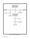
1 Tests multiplexer inputs. First measure voltage at Ul5 pin 4. Toggle S3 switch 5 until voltage at Ul5 pin 8 equals the
voltage at U15 pin 4. Now each time S3 switch 5 is toggled, the multiplexer will sequence through its inputs. The input
of the A/D (Ul2-9) will be equal to the output of the multiplexer. Because the A/D is continually reading, its output
(Ul2-20) should pulse.
2 Continuously reads the contents of location 0 of EEPROM. Check pulses at U22 pin 4.
3 Tests relays K601-K606. Toggling S3 switch 5 sequences through the relays. A relay is off when both ends of the coil
are at +12V. A relay is on when one end is pulled low. A particular relay will energize every 5th toggle on S3 switch 5.
Note that K607 is not tested.