


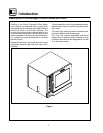
Installation
9
Plumbing Connections
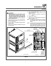
WATER CONNECTION -- CNV14E ONLY
NOTE: Hot wat e r maximizes steam product ion but
is not requ ired. Co ld water ma y be su pplie d
to bot h inlets if hot water is not a v aila ble .
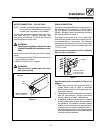
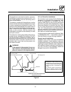
Connect the appliance to quality water via a pres-
sure hose with 3/4” (19mm) couplings. See
Figure 6 for connections. A shut off valve is to be
provided adjacent to the oven.
WARNING!!
Operating the appliance without the water
regu lator installed will inv alidate you r war-
ranty.
Water must meet the following minimum require-
ments:
D
Total Dissolved Solids (TDS) content will not ex-
ceed 30 parts per million.
D
WaterPHmustbe7.0orhigher
WARNING!!
The use of poor quality water will invali-
date your warranty.
CNV-14E
Cold
Water
Water Connections
Rear of Appliance
Figure 6
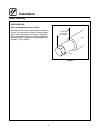
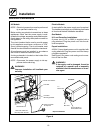
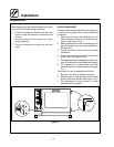
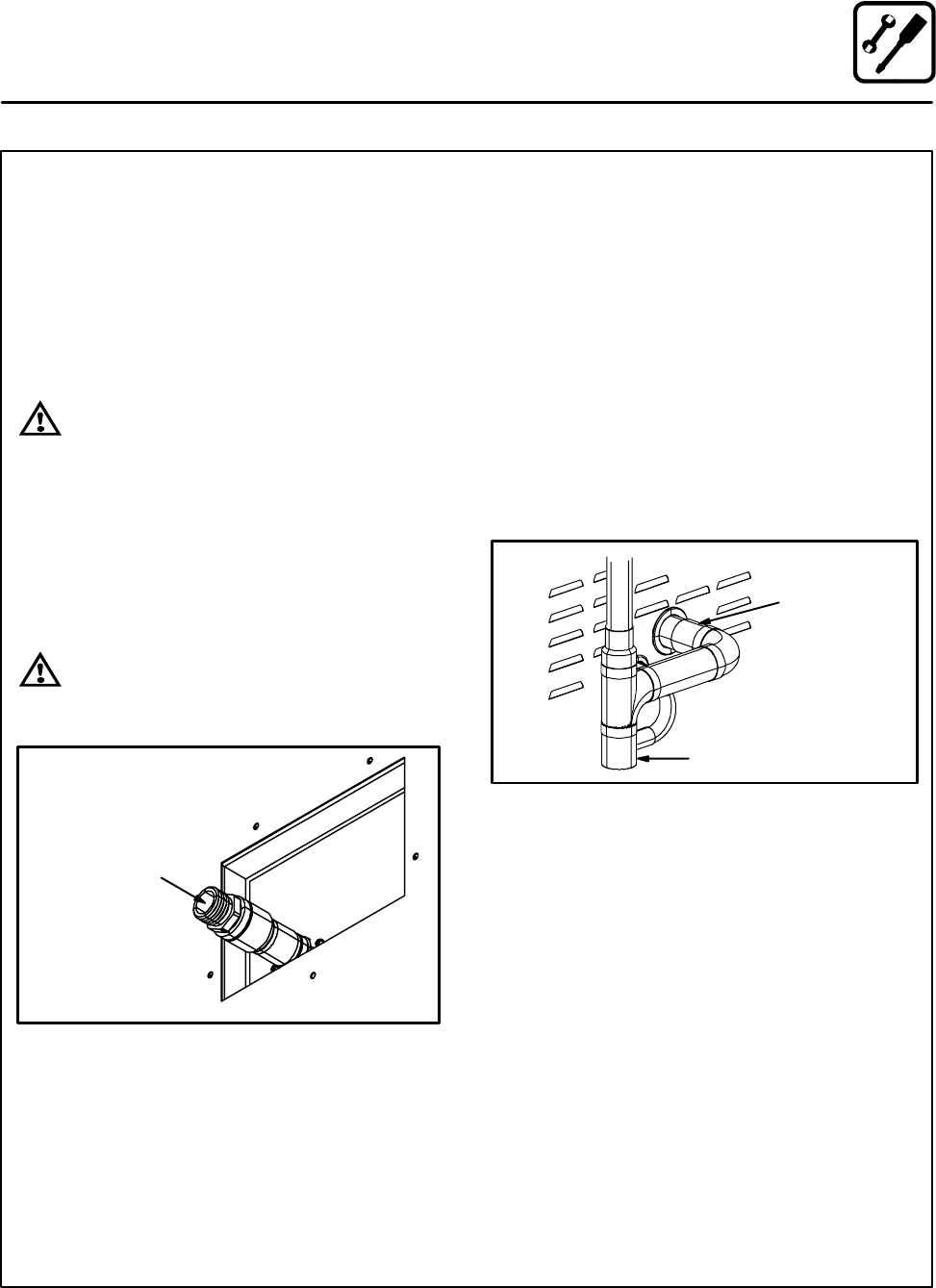
DRAIN CONNECTION
The steam vent assemblies are constructed of 2”
DWV copper piping reduced to 1-1/2 DWV pipe. If
the vent system is not purchased a s an option
(R9381), Blodgett Combi recommends plumbing
the oven as show n in Figure 7.
The steam vent should be run to an open floor
drain avoiding flexible hose that could sag and al-
low trapped water to accumulate. The customer
must supply the piping from the oven to the drain.
Connect the drip pan drain to the steam vent with
1.125 I.D. hose.
Use the drain vent assembly and a 2” (50.8mm)
pipe for drain connection.
Customer supplied
2” (50.8mm) drain
waste vent piping
Coupling
Figure 7
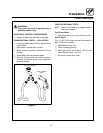
Specific water/drain connection for City of Los
Angeles
1. Each drain line from the appliance shall be
routedwithoutdipsorsagstoterminate
above the flood level rim of an approved indi-
rect waste receptor.
2. The appliance shallbe installed in accordance
with the manufacturer’s printed instructions
and the LAPC and LAMC, 1999 editions.
3. A backflow protection device shall be installed
on the p o table water s ystem d ir ectl y ahead of
the appli ance. The backfl ow protectio n devi ce
shall be any of the following: an approved pres-
sure ty pe vacuum breaker i nstall ed at least 12”
above the highest poi nt of use, a double check
valve backflo w preventer or a reduced pressure
principal backflo w preventer.