


A
WAmING
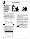
● All ranges can tip.
● Injury could result.
. M the Anti-tip device
packed with the range.
. See the Instigation
Instructions.
● The Anti-tip device must
remain engaged.
StabilityDevice Instillation Instructions
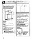
1. Onthe rightsideof thecutoutor installation 3. If mountingintowoodflooring,drill3/32”holesas
locationmeasure5ti” fromthebackwallforward marked.If mountingintoconcrete,usea masonry
andmark a point.Repeaton theleft-handside,then drillbitanddrill3/16”holes.Insertplasticanchors
drawa straightlinebetweenthepoints.
intoconcreteholes.Positionthebracketandmount
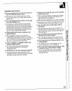
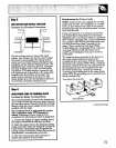
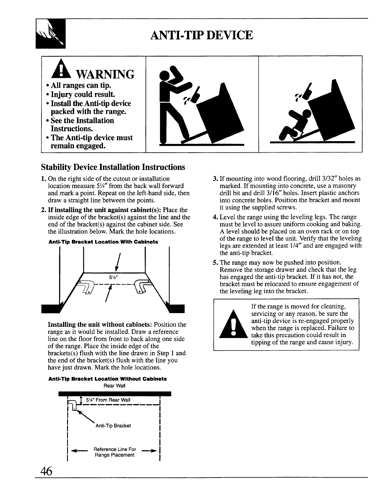
2. If installing the unit against cabinet(s): Placethe
it usingthesuppliedscrews.
insideedge-ofthebrac~et(s)againstthe”lineandthe 4. Leveltherangeusingthelevelinglegs.Therange
endof thebracket(s)againstthecabinetside.See mustbe levelto assureuniformcookingandbaking.
theillustrationbelow.Marktheholelocations. A levelshouldbeplacedonan ovenrack oron top
Anti-fip Bracket Location Wth Cabinets
of therangeto lev~ltheunit.Verifythattheleveling
11,11
legs are extended at least 1/4”and are engaged with
the anti-tip bracket.
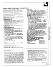
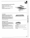
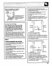
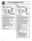
Installingtheunitwithoutcabinets:Position the
range as it would be installed. Draw a reference
line on the floor from front to back along one side
of the range. Place the inside edge of the
brackets(s) flush with the line drawn in Step 1 and
the end of the bracket(s) flush with the line you
have just drawn. Mark the hole locations.
Anti-~p Bracket Location Wthout Cabinets
RearWall
M
I
Anti-~pBracket
I
I
I
i
i
I ~ ReferenceUneFor ~ I
I
RangePlacement
I
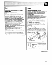
5. me rangemaynowbe pushedintoposition.
Removethe storagedrawerand checkthattheleg
hasengagedtheanti-tipbracket.If it hasnot,the
bracketmustberelocatedto ensureengagementof
thelevelinglegintothebracket.
If therangeismovedfor cleaning,
A
servicing or any reason, be sure the
anti-tip device is re-engaged properly
when the range is replaced. Failure to
take this precaution could result in
tipping of the range and cause injury.