


– 45 –
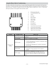
Electronic Oven Control
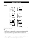
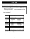
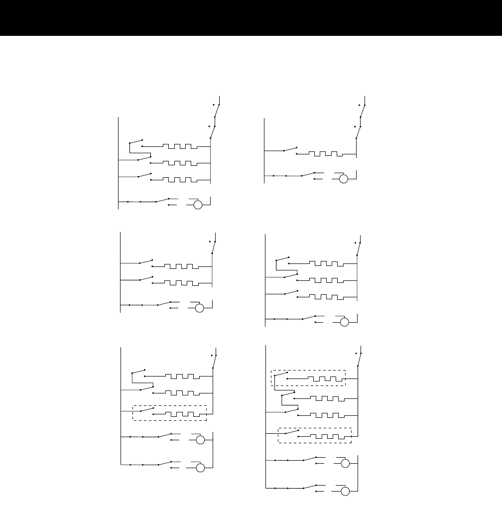
Oven Circuits
UPPER OVEN
BAKE & SELF CLEAN
BAKE
SPEEDON/OFF
K8
K3
K7
K5 K4
LOW
HIGH
COOLING FAN
N
DLB
Relay*
K14
L2
L1
INNER BROIL
OUTER BROIL
M
UPPER OVEN
BROIL
SPEEDON/OFF
K3
K5 K4
LOW
HIGH
COOLING FAN
N
L1
INNER BROIL
M
DLB
K14
L2
Relay*
LOWER OVEN
BROIL
SPEEDON/OFF
K8
K3
K5 K4
LOW
HIGH
COOLING FAN
N
DLB
K14
L2
L1
INNER BROIL
OUTER BROIL
M
LOWER OVEN
SELF CLEAN
BAKE
SPEEDON/OFF
K8
K3
K7
K5 K4
LOW
HIGH
COOLING FAN
N
DLB
K14
L2
L1
INNER BROIL
OUTER BROIL
M
LOWER OVEN
BAKE & CONVECTION ROAST
BAKE
DIRECTIONON/OFF
K3
K7
K5 K4
CW
CCW
CONVECT FAN
DLB
K14
L2
L1
INNER BROIL
M
K8
OUTER BROIL
ONLY USED DURING PREHEAT
SPEEDON/OFF
K5 K4
LOW
HIGH
COOLING FAN
N
M
LOWER OVEN
CONVECTION BAKE
BAKE
DIRECTIONON/OFF
K3
K7
K5 K4
CW
CCW
CONVECT FAN
DLB
K14
L2
L1
INNER BROIL
M
K8
OUTER BROIL
ONLY USED DURING PREHEAT
SPEEDON/OFF
K5 K4
LOW
HIGH
COOLING FAN
N
M
NOT USED DURING PREHEAT
CONVECTION
K10
All closed switches shown above are closed during the respective cooking cycle. All open switches cycle
during the respective cooking cycle.
Note:
Relay – This relay is external to the control boards and is mounted on the back cover of the unit. This •
relay is connected to the upper plunger switch and opens and closes based on the plunger position.
Element Relay Cycling – All cavity elements cycle during preheat and once the oven cooking •
temperature is reached. However, only the bake, inner broil, and convection elements come on one at a
time (multiple elements are not energized).
Power Sharing Mode – The outer broil elements are disabled when both ovens are in operation. •
Relay/Board Designations – All relays listed above for each oven correspond to their respective oven •
relay boards except for the cooling and convection fans. The cooling fan is located on the upper oven
relay board, and the convection fan is located on the lower oven relay board.