– 48 –
Diagnostics and Service Information
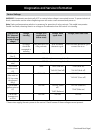
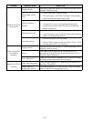
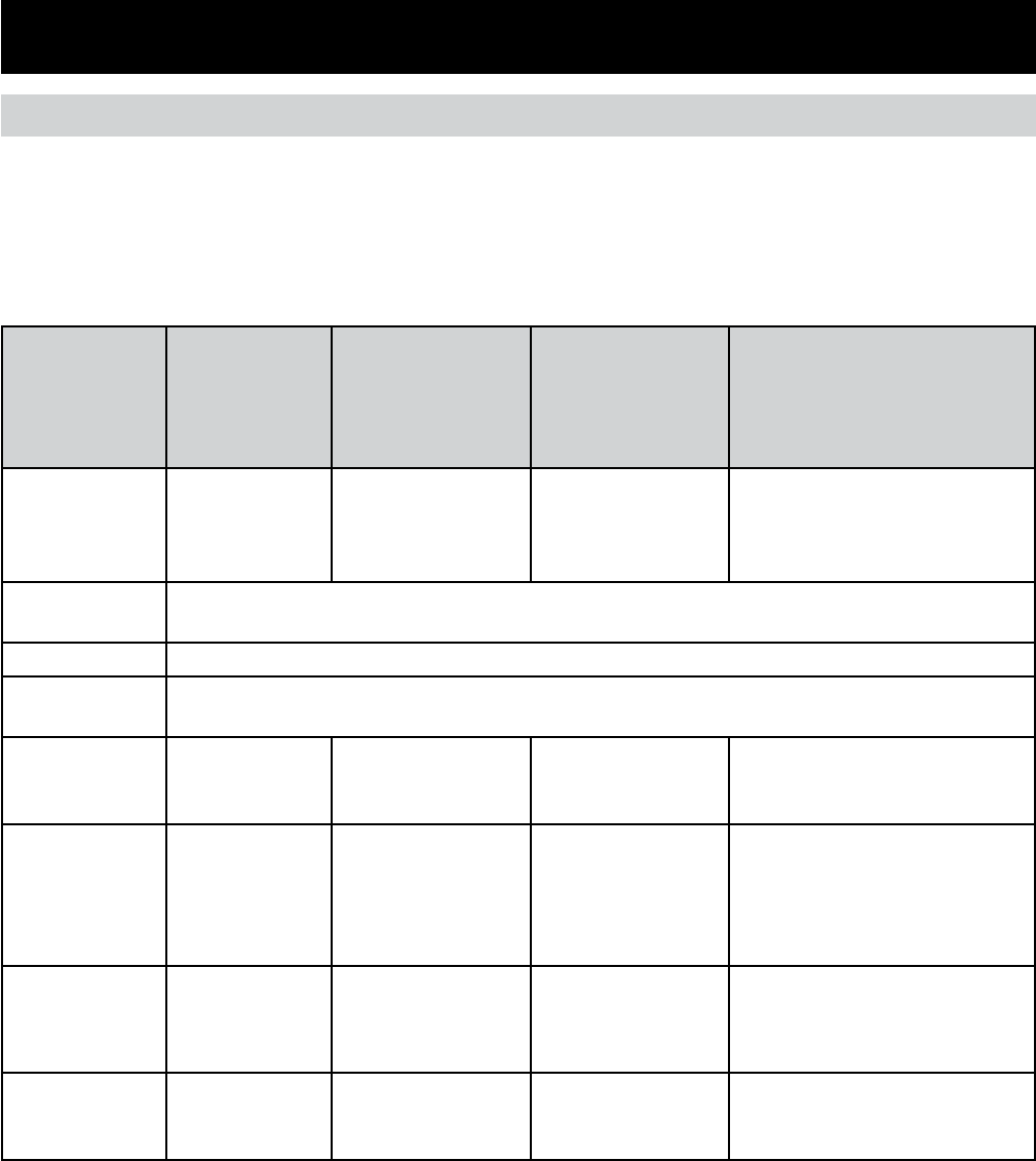
Control Voltage
WARNING: Components are electrically HOT on control when voltage is connected to oven. To prevent electrical
shock, use extreme caution when diagnosing oven with outer covers removed and power on.
Note: Mode and temperature selection is necessary for operation of relay contacts. This model incorporates
Double Line Break, meaning there is no voltage on the elements when the control is in standby.
Terminals on
ERC (element
terminals are
on top of large
relays)
Voltage,
standby
Voltage, broil
mode active
(either oven)
Voltage, bake
upper oven
Voltage, bake lower oven
No relays
should be
energized in
standby
Only broil and DLB
relay activate
Broil and bake
elements cycle
Broil and bake elements cycle
convect fan is on
J20 (Pins 1 to
Pins 3)
120V (if not, harness may be bad*
J14 to J11 120V (if not, harness may be bad*
J14 to J20 (red
wire)
120V (if not, harness may be bad*
J14 to Broil
(violet wire on
K3)
˜OVAC ˜OVAC (Broil on)
˜240 VAC (Broil off)
˜OVAC (Broil on)
˜240 VAC (Broil off)
J14 to Conv.
(blue wire on
K10 Lwr oven
relay board
only)
˜240 VAC N/A ˜OVAC (Conv. on)
˜240 VAC (Conv. off)
J14 to Bake
(yellow wire on
K7)
˜240 VAC ˜240 VAC (Bake
off)
˜OVAC (Bake on)
˜240 VAC (Bake off)
˜OVAC (Bake on)
J14 to DBL
(orange wire
on K14)
˜240 VAC ˜240 VAC ˜240 VAC
(Continued Next Page)
* These wires supply the main power to the control. Check harness if these voltages are not present.


