


31
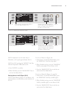
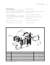
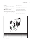
THE CONTROL SYSTEM
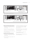
The Control System signals, senses, commands, and
actuates the oven’s other components. For a
schematic that includes all Control System compo-
nents, see Figure 61, page 61. For more compre-
hensive hardware descriptions, see page 69.
This section contains:
Serviceable Component Information and
Replacement Instructions
Parts and Part Numbers
Troubleshooting
S
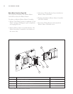
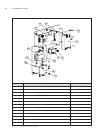
ERVICEABLE COMPONENTS
The following components of the Control System
may at some point need to be replaced:
Blower Motor Controller
Cooling Fans – Inlet and Exhaust
Display
Display Keypad
Door Switch
Fuses
I/O Control Board
Power Supply
Rack Oscillator Motor
Relay
Smart Card Reader
Solid State R
elay
Thermocouple – CC
Thermocouple – EC
Thermostat – Cooling Fan
Thermostat – Hi-Limit
Voltage Sensor