


53
THE IMPINGEMENT CIRCUIT
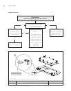
The Impingement Circuit provides the high
temperature airflow necessary to brown and
cook food items. For a schematic that includes
all Impingement Circuit components, see
Figure 61, page 61. For more comprehensive
hardware descriptions, see page 69.
This section contains
Serviceable Component Information and
Replacement Instructions
P
arts and Part Numbers
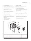
SERVICEABLE COMPONENTS
The following components of the Impingement
Circuit may at some point need to be replaced.
Blower M
otor
Heater Element
Jetplates (Top and Bottom)
Swing Arm Assembly
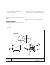
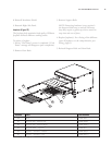
Blower Motor (Figure 55)
A Brushless DC Switch reluctance type. Its top
speed is 7200 RPM at 3/4 HP.
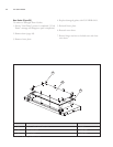
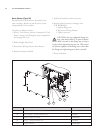
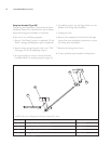
To replace a defective Blower Motor:
1. Ensure “Cool Down” process is completed (“Cool
Down” message will disappear upon completion)
and unplug the oven.
2. Remove Blower Motor Controller (see page 32).
3. Disconnect wiring at Blower Motor Controller.
4. Remove Blower Motor Cover.
5. Replace defectiv
e motor with P/N HHB-8106.
6. Reconnect wiring and reinstall Blower Motor
Controller/Blower Motor Cover.
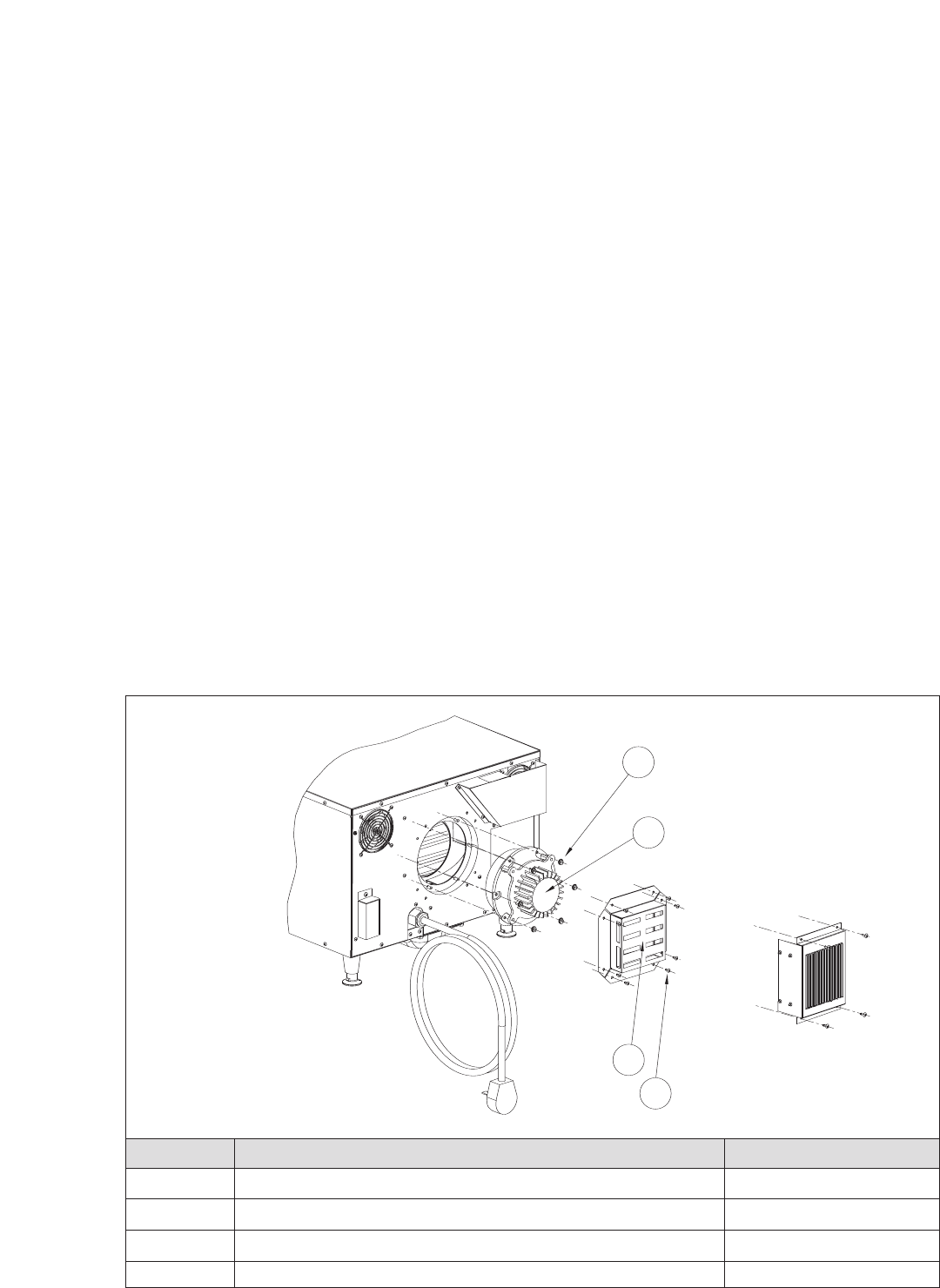
NUMBER
PART PART NUMBER
71 Nut – Blower Motor (x6) 100905
72 Blower Motor HHB-8106
73 Screw – Blower Motor Cover (x8) 101688
74 Blower Motor Cover NGC-1081
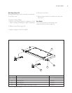
: R
emo
ving the Blower Motor
71
72
74
73