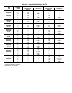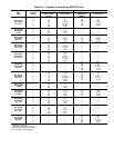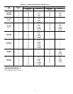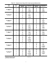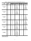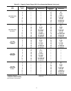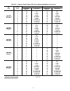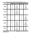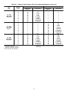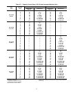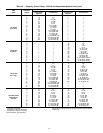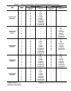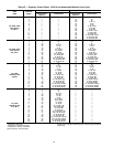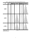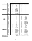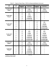
Table 4B — Capacity Control Steps, 080-110 and Associated Modular Units (cont)
UNIT
30GN
CONTROL
STEPS
LOADING SEQUENCE A LOADING SEQUENCE B
%
Compressors
%
CompressorsDisplacement Displacement
(Approx) (Approx)
110, 290B,
315B (50 Hz)
A1†**,B1†
1 8 A1†† — —
2 17 A1* — —
325 A1 — —
4 33 A1††,B1 — —
5 42 A1*,B1 — —
6 50 A1,B1 — —
7 58 A1††,A2,B1 — —
8 67 A1*,A2,B1 — —
9 75 A1,A2,B1 — —
10 83 A1††,A2,B1,B2 — —
11 92 A1*,A2,B1,B2 — —
12 100 A1,A2,B1,B2 — —
110, 290B,
315B (50 Hz)
A1†,B1†**
1 — — 8 B1††
2 — — 17 B1*
3— — 25 B1
4 — — 33 A1,B1††
5 — — 42 A1,B1*
6 — — 50 A1,B1
7 — — 58 A1,B1††,B2
8 — — 67 A1,B1*,B2
9 — — 75 A1,B1,B2
10 — — 83 A1,A2,B1††,B2
11 — — 92 A1,A2,B1*,B2
12 — — 100 A1,A2,B1,B2
110, 290B,
315B (50 Hz)
A1†**,B1†**
1 8 A1†† 8 B1††
2 17 A1* 17 B1*
325A1 25B1
4 33 A1††,B1 33 A1,B1††
5 42 A1*,B1 42 A1,B1*
6 50 A1,B1 50 A1,B1
7 58 A1††,A2,B1 58 A1,B1††,B2
8 67 A1*,A2,B1 67 A1,B1*,B2
9 75 A1,A2,B1 75 A1,B1,B2
10 83 A1††,A2,B1,B2 83 A1,A2,B1††,B2
11 92 A1*,A2,B1,B2 92 A1,A2,B1*,B2
12 100 A1,A2,B1,B2 100 A1,A2,B1,B2
*Unloaded compressor.
†Compressor unloader, standard.
**Compressor unloader, accessory.
††Two unloaders, both unloaded.
NOTE: These capacity control steps may vary due to lag compressor
sequencing.
14


