


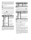
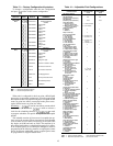
Factory Configuration Codes — allows entry into
the factory configuration subfunction. Under this subfunc-
tion, there are 7 groups of configuration codes that are down-
loaded at the factory. Each group is made up of 8 digits. If
processor module is replaced in the field, these 7 groups of
configuration codes must be entered through the keypad
and display module. Factory configuration codes (groups 1
through 7) that apply to the particular Flotronic™ II chiller
being serviced are found on a label diagram located inside
the control box cover. See Table 13 for a summary of factory
configuration subfunction keystrokes.
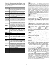
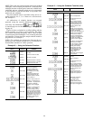
Adjustable Field Configurations — After logging on, press
to enter subfunction. The subfunction allows opera-
tion of the chiller to be customized to meet the particular
needs of the application. The chiller comes from the factory
preconfigured to meet the needs of most applications. Each
item should be checked to determine which configuration
alternative best meets the needs of a particular application.
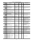
See Table 14 for factory loaded configuration codes and al-
ternative configurations.
If processor module is replaced, the replacement module
is preloaded with factory default configuration codes. Each
configuration code must be checked and, if necessary, re-
configured to meet needs of the application. See Table 14 for
pre-loaded service replacement configuration codes.
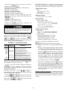
Service Configuration Codes — Press to enter the
service configuration subfunction. The first 2 items under this
subfunction are 2 groups (8 digits each) of configuration codes
that are downloaded at the factory. If processor module is
replaced in the field, the 2 groups of configuration codes must
be entered through the keypad and display module. The
2 groups of configuration codes (groups 8 and 9) that apply
to the unit being serviced can be found on a label diagram
inside the control box cover. See Table 13 for keystroke in-
formation to enter configuration codes 8 and 9. The remain-
ing items in this subfunction are read-only data provided to
assist in service evaluations.
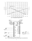
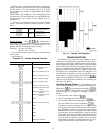
SCHEDULE FUNCTION — This function provides a means
to automatically switch chiller from an occupied mode to an
unoccupied mode. When using schedule function, chilled fluid
pump relay must be used to switch chilled fluid pump on
and off. Connections for chilled fluid pump relay are: TB3-3
and TB3-4. The chilled fluid pump relay starts chilled fluid
pump but compressors do not run until remote chilled fluid
pump interlock contacts are between TB6-1 and TB6-2 are
closed and leaving chilled fluid temperature is above set point.
If a remote chilled fluid pump interlock is not used, the first
compressor starts (upon a call for cooling) approximately
one minute after chilled fluid pump is turned on.
The unit can be programmed for inactive, single set point,
or dual set point operation.
When unit is configured for inactive, chilled fluid pump
relay remains energized continuously but is not used since
chiller is usually controlled by remote chilled fluid pump in-
terlock contacts.
When unit is configured for single set point operation, chilled
fluid pump relay is energized whenever chiller is in occu-
pied mode regardless of whether chiller is running. When
chiller is in unoccupied mode, chilled fluid pump relay is
not energized.
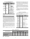
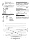
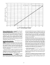
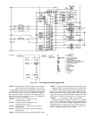
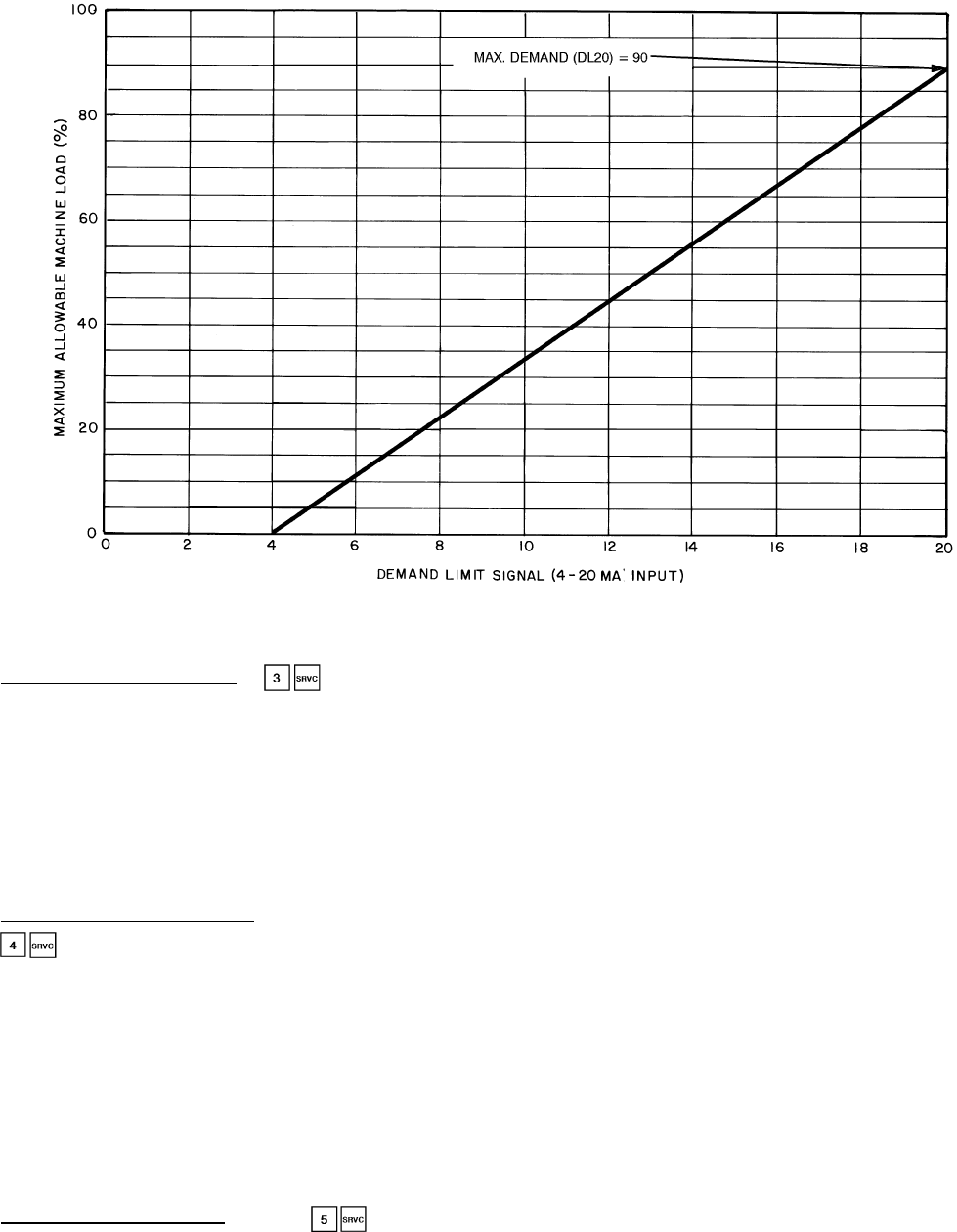
Fig. 9 — 4-20 mA Demand Limiting
44