


If accessory unloaders are desired, an accessory unloader
package is used. Package includes a suction cutoff unloader
head package. The 24-v coil in the package can be used
for 040-110, 130 (60 Hz), and associated modular units
(Table 1). A 115 v or 230 v coil must be used for 130
(50 Hz), 150-210, and associated modular units (Table 1).
Coil voltage depends on control circuit voltage. Consult cur-
rent Carrier price pages for appropriate part numbers.
NOTE: The accessory package will include all necessary com-
ponents and wiring with the following exceptions: The field
must provide screws, and on the 130-210, and associated modu-
lar units, the field must also supply a 20 vdc (part number
HK35AB001) unloader relay and wire (90° C or
equivalent).
Installation
1. Be sure all electrical disconnects are open and tagged be-
fore any work begins. Inspect the package contents for
any damage during shipping. File a claim with the ship-
per if damage has occurred.
2. For ease of installation, factory-supplied wiring for the
additional unloader is provided in the compressor
harness.
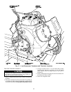
3. Install the additional unloader cylinder head on the lead
compressor, A1 or B1, according to instructions provided
by the compressor manufacturer in the accessory
package.
4. Continue installation per either 040-110, 130 (60 Hz) units
or 130 (50 Hz), 150-210 units section as appropriate.
040-110, 130 (60 Hz) UNITS (AndAssociated Modular Units)
1. Wire the solenoid before any field wiring begins. Wiring
between components and control box must be enclosed
in conduit. All local electrical codes and National Elec-
trical Code (NEC) must be followed. Factory wires are
provided in the compressor harness to connect the sole-
noid. These wires are in the compressor control box.
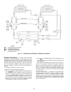
2. Wire the control side. Open the left side control box door
and remove inner panel. Using the holes provided and
field-supplied screws, install field-supplied transformer above
the DSIO-LV on the control panel.
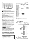
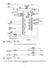
Wire the primary side of the transformer in parallel with
TRAN4. See Fig. 23. This supplies transformer with proper
line voltage. Be sure to connect proper tap of the trans-
former to ensure supply of proper secondary voltage.
Wire the secondary side of transformer to DSIO-LV - J5-9,
and a jumper from DSIO-LV - J5-9 to DSIO-LV - J4-9.
Wire the secondary common to TB7-2. Connect the trans-
former ground to ground hole supplied near the trans-
former. These connections provide DSIO with necessary
power to energize the solenoid coils.
3. When all connections are made, check for proper wiring
and tight connections. Replace and secure inner panel.
Restore power to unit.
4. Configure the processor. With the addition of extra un-
loaders, the unit configuration has changed. To change
the configuration of the processor, enter the service func-
tion using the keypad and display module. Before any
changes can be made, the LOCAL/ENABLE-STOP-
CCN switch must be in the STOP position, and the ser-
vicer must log on to the processor.
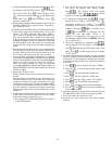
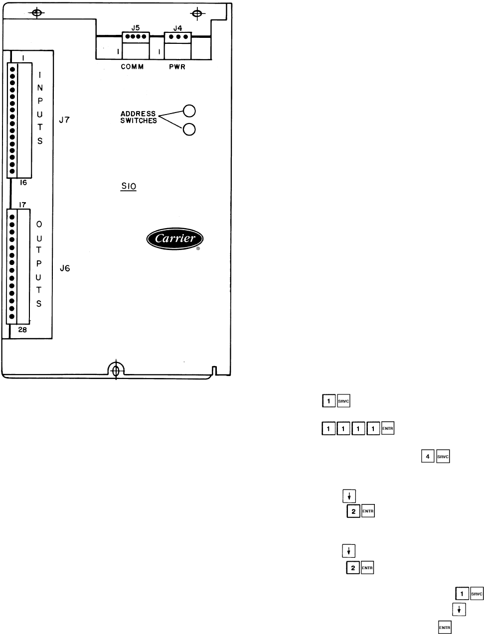
a. Press . Keypad LCD displays the word
PASSWORD.
b. Enter . Keypad LCD displays
LOGGEDON.
c. To change configuration, press . Keypad LCD
displays FLD CFG.
d. If an additional unloader was added to compressor
A1, press until NULA 1 appears in keypad dis-
play. Press for the number of unloaders on
circuit A. Keypad display now reads NULA 2.
e. If an additional unloader was added to compressor
B1, press until NULB 1 appears in keypad dis-
play. Press for the number of unloaders on
circuit B. Keypad display now reads NULB 2.
f. When configuration is complete, press . Key-
pad display reads LOGGEDON. Press until key-
pad display reads LOG OFF. Press . Keypad dis-
play reads EXIT LOG.
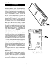
LEGEND
COMM — Communications Bus
PWR — Power
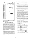
Fig. 22 — 4 In/4 Out Module (SIO)
65