


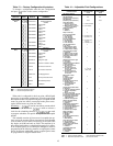
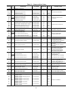
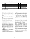
Table 16 — Alarm and Alert Codes (cont)
DISPLAY
ALARM
DESCRIPTION
ACTION TAKEN CIRCUIT RESET
PROBABLE CAUSEOR
ALERT
BY CONTROL PUMPDOWN METHOD
63 Alarm Complete unit shutdown Alarm only — Auto. Check individual alarms
64
Alert
Loss of charge, circuit A Circuit cannot start — Auto. Refrigerant leak or transducer
failure65 Loss of charge, circuit B Circuit cannot start — Auto.
66 Alarm FSM communication loss FSM forces removed — Auto. Wiring faulty or module failure
67 Alarm Transducer calibration date code failure Unit cannot start — Auto. Incorrect date code entered
68,69 — Not used — — — —
70 Alert High leaving chilled fluid temperature Alarm only — Auto. Building load greater than unit capacity,
low water/brine flow, or compressor
fault. Check for other alarms or alerts.
LEGEND
CPCS — Compressor Protection Control Module
FSM — Flotronic™ System Manager
PS — Power Supply
WSM — Water System Manager
*Reset automatic first time, manual if repeated same day.
Possible causes of failure:
1. High-Pressure Switch Open — High-pressure switch for
each compressor is wired in series with 24-v power that
energizes compressor control relay. If high-pressure switch
opens during operation, compressor stops. This is
detected by microprocessor through the feedback
terminals.
2. DSIO-LV or DSIO-EXV Module Failure — If a DSIO-LV
relay module relay fails open or closed, microprocessor
detects this, locks compressor off, and indicates an
error.
3. Wiring Errors — If a wiring error exists causing CPCS,
CR, or feedback switch to not function properly, micro-
processor indicates an error.
4. Processor (PSIO) Failure — If hardware that monitors
feedback switch fails, or processor fails to energize relay
module relay to on, an error may be indicated.
NOTE: The control does not detect circuit breaker fail-
ures. If a circuit breaker trips on lead compressor in a
circuit, a low oil pressure failure is indicated. On the other
compressors, no failure is indicated.
5. Ground Fault Module on 130-210 and associated modu-
lar units (CGFA or CGFB) Open — Module contacts are
in lead compressor circuits, but ground fault could be in
any compressor in affected circuit.
Ground fault of any 040-110 and associated modular unit
compressor (field-supplied accessory on 040-060 and 070,
60 Hz units; standard on 070, 50 Hz and 80-110 and as-
sociated modular units) will cause a trip.
6. Checkout Procedure — Shut off main power to unit. Turn
on control power, then step through subfunc-
tion to proper compressor number (i.e., failure
code 5 is compressor B1). Next, energize the step. If step
works correctly, then failure code is caused by:
• HPS (high-pressure switch) open
• Misplaced feedback wire from J4 and J5 terminals
• Ground wire and 24-v feeds reversed on one or more
points on J3
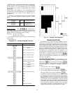
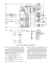
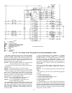
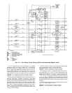
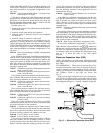
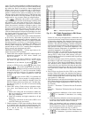
Compressor Alarm/Alert Circuit — For compres-
sor A1 circuit, processor closes contacts between J4 termi-
nals 2 and 3 to start compressor. See Fig. 11A-11C. Safeties
shown to left of J4 must be closed in order for power to
reach compressor control relay, and the feedback input ter-
minals on J3.
Failure of power to terminal 1 on J3, when contacts be-
tween 2 and 3 on J4 should be closed, causes a code 1 alert.
Terminal 2 on J3 is the other leg of the compressor A1
feedback channel. It is connected to the 24-v common.
NOTE: Similar connections for each compressor can be fol-
lowed on the unit wiring diagrams located on the unit.
Code 9 Leaving fluid thermistor failure (alarm)
Code 10 Entering fluid thermistor failure (alarm)
If temperature measured by these thermistors is outside
range of –40 to 240 F (–40 to 116 C), unit shuts down after
going through a normal pumpout. Reset is automatic if tem-
perature returns to the acceptable range, and unit start-up fol-
lows normal sequence. The cause of the fault is usually a
bad thermistor, wiring error, or loose connection.
Code 19 Compressor A1 suction sensor failure (alert)
Code 20 Compressor B1 suction sensor failure (alert)
On units with thermistors, if temperature measured by these
thermistors is outside the range of –40 to 240 F (–40 to
116 C), affected circuit shuts down after going through a nor-
mal pumpout. Other circuit continues to run. Reset is auto-
matic if temperature returns to the acceptable range, and cir-
cuit start-up follows normal sequence. The cause of this fault
is usually a bad thermistor, wiring error, or loose
connection.
On units with transducers, if the saturated suction tem-
perature is greater than the leaving fluid temperature plus
10° F (5.5 C) for more than 5 minutes, the affected circuit
shuts down (after going through normal pumpout). The reset
is automatic if the saturated suction temperature returns to
the acceptable range and start-up follows the normal se-
quence. The cause of this fault is usually a bad transducer,
a wiring error, or a loose connection.
50