


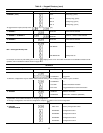
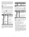
Example 5B—4to20mAandInternally or
Externally Powered Reset
In this example, the unit set point is reset from full load
at 4 mA to a maximum reset value of 10 F (5.5 C) at
20 mA. Internally powered 4 to 20 mA option is used in this
example.
NOTE: To use externally powered reset, when CRTYP
appears, press so CRTYP 4 appears in the
display. The remainder of the information in the fol-
lowing example applies to either type of reset.
KEYPAD
ENTRY
DISPLAY
RESPONSE
COMMENTS
FLD CFG
CRTYP 0 Scroll past to reset type
CRTYP 1
Internally powered reset
selected
RESET
CRT1 0 Reset at 20 mA is 0
CRT1 10 Reset at 20 mA is 10
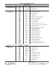
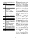
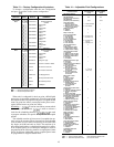
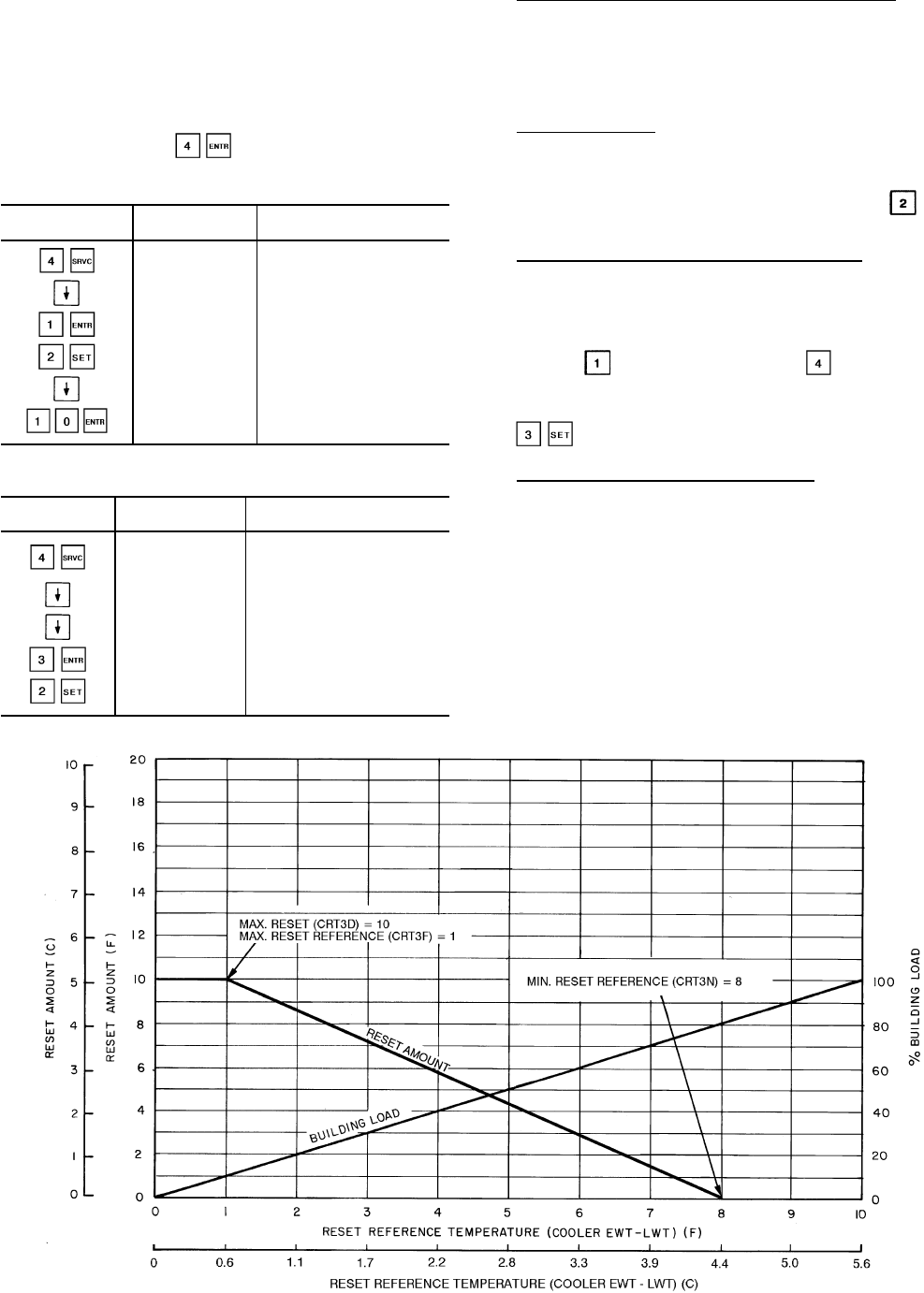
Example 5C — Using Return Fluid
Temperature Reset
KEYPAD DISPLAY
COMMENTS
ENTRY RESPONSE
FLD CFG
Field configuration
subfunction of
service function
CSPTYP X Scroll past single/dual
CRTYP 0
Display shows no reset
type has been selected
CRTYP 3
Return fluid temperature
is selected and activated
RESET Reset set points
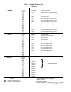
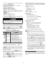
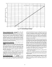
Temperature Reset Based on External Temperature — If de-
sired, temperature reset can be based on an external tem-
perature, such as space or outdoor-air temperature. This re-
quires a thermistor (T10, Part No. 30GB660002) located in
the space or outdoor air and wired to terminals as follows
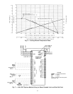
(also see Field Wiring section on page 69 and Fig. 6):
4 in/4 out Module — J7-15 and J7-16.
At the field configuration step, enter set points as de-
scribed in Examples 5A-5C on pages 39 and 40. Then
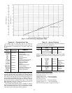
select external temperature reset by entering when
CRTYP 0 appears. See Fig. 7.
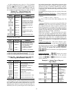
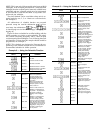
Temperature Reset Based on 4-20 mA Signal— If desired,
temperature reset can be based on a 4-20 mA signal. For
proper connections, refer to Field Wiring section on
page 69 and Fig. 8.
At the field configuration step, select 4-20 mA reset by
entering (internally powered) or (externally pow-
ered) when CRTYP 0 appears. Then enter set points as de-
scribed previously in Examples 5A-C. See Fig. 8.
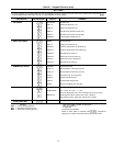
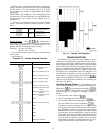
Subfunction displays demand limit set points.
Demand Limit, 2-Stage Switch Control — This control has
been designed to accept demand limit signals from a build-
ing load shedding control. The demand limit function pro-
vides for 2 capacity steps. The keypad is used to set the 2
demand limit set points, which range from 100 to 0% of ca-
pacity. Capacity steps are controlled by 2 field-supplied re-
lay contacts connected to the designated chiller terminals.
(See Field Wiring section on page 69 and Fig. 7.)
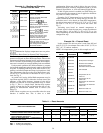
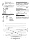
Fig. 5 — Cooling Return Fluid Reset
40