


reading correctly. Connect a calibrated gage to lead
compressor suction or discharge pressure connection
to check transducer reading.
e. Make sure transducer leads are properly connected in
junction box and at processor board. Check trans-
former 5 output. Check voltage transducer 5 vdc
Ϯ .2 v.
When above checks have been completed, check ac-
tual operation of EXV by using procedures outlined in
this step.
6. Check operation of EXV.
a. Close liquid line service valve of circuit to be checked,
and run through the test step ( ) for lead com-
pressor in that circuit to pump down low side of sys-
tem. Repeat test step 3 times to ensure all refrigerant
has been pumped from low side.
NOTE: Be sure to allow compressors to run for the
full pumpout period.
b. Turn off compressor circuit breaker(s). Close com-
pressor discharge service valves and remove any re-
maining refrigerant from low side of system.
c. Remove screws holding top cover of EXV. Carefully
remove top cover. If EXV plug was disconnected dur-
ing this process, reconnect it after cover is removed.
When removing top cover, be careful to avoid dam-
aging motor leads.
d. Enter appropriate EXV test step for EXVA or
EXVB in the outputs subfunction of the test function
( ). Press to initiate test. With
cover lifted off EXV valve body, observe operation of
valve motor and lead screw. The motor should turn
counterclockwise, and the lead screw should move up
out of motor hub until valve is fully open. Lead screw
movement should be smooth and uniform from
fully closed to fully open position. Press to
check open to closed operation.
If valve is properly connected to processor and receiv-
ing correct signals, yet does not operate as described
above, valve should be replaced.
Operation of EXV valve can also be checked without
removing top cover. This method depends on opera-
tor’s skill in determining whether or not valve is mov-
ing. To use this method, initiate EXV test and open
valve. Immediately grasp EXV valve body. As valve
drives open, a soft, smooth pulse is felt for approxi-
mately 26 seconds as valve travels from fully closed
to fully open. When valve reaches end of its opening
stroke, a hard pulse is felt momentarily. Drive valve
closed and a soft, smooth pulse is felt for the 52 sec-
onds necessary for valve to travel from fully open to
fully closed. When valve reaches end of its stroke, a
hard pulse is again felt as valve overdrives by 50 steps.
Valve should be driven through at least 2 complete cycles
to be sure it is operating properly. If a hard pulse is
felt for the 26-second duration, valve is not moving
and should be replaced.
The EXV test can be repeated as required by enter-
ing any percentage from 0 ( ) to 100 to initiate
movement.
If operating problems persist after reassembly, they may
be due to out-of-calibration thermistor(s) or intermittent
connections between processor board terminals and EXV
plug. Recheck all wiring connections and voltage signals.
Other possible causes of improper refrigerant flow con-
trol could be restrictions in liquid line. Check for plugged
filter drier(s) or restricted metering slots in the EXV. For-
mation of ice or frost on lower body of electronic ex-
pansion valve is one symptom of restricted metering slots.
However, frost or ice formation is normally expected when
leaving fluid temperature from the cooler is below 40 F.
Clean or replace valve if necessary.
NOTE: Frosting of valve is normal during compressor
test steps and at initial start-up. Frost should dissipate af-
ter 5 to 10 minutes operation in a system that is operating
properly. If valve is to be replaced, wrap valve with a wet
cloth to prevent excessive heat from damaging internal
components.
Thermostatic Expansion Valve (TXV) — Refer to
base unit Installation Instructions for TXV information
(30GN040,045 with optional brine only).
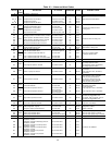
Thermistors — All thermistors are identical in their tem-
perature vs. resistance performance. Resistance at various tem-
peratures are listed in Tables 17 and 18.
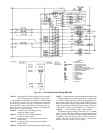
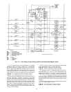
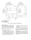
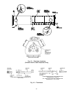
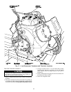
LOCATION — General location of thermistor sensors are
shown in Fig. 14.
Cooler Leaving Fluid Thermistor (T1) — T1 is located in
leaving fluid nozzle. The probe is immersed directly in the
fluid. All thermistor connections are made through a
1
⁄
4
-in.
coupling. See Fig. 16. Actual location is shown in Fig. 14
and 15.
Cooler Entering Fluid Thermistor (T2) — T2 is located in
cooler shell in first baffle space near tube bundle. Thermistor
connection is made through a
1
⁄
4
-in. coupling. See Fig. 16.
Actual location is shown in Fig. 14 and 15.
Compressor Suction Gas Temperature Thermistors (T7 and
T8) — T7 and T8 are located in lead compressor in each
circuit in suction passage between motor and cylinders, above
oil pump. They are well-type thermistors. See Fig. 14
and 15.
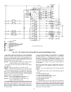
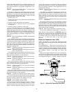
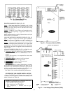
THERMISTOR REPLACEMENT (T1, T2, T7, T8)
Thermistors are installed directly in fluid Relieve all pres-
sure using standard practices or drain fluid before re-
moving.
Proceed as follows (see Fig. 16):
To replace thermistor sensor T2:
1. Remove and discard original thermistor and coupling.
IMPORTANT: Do not disassemble new coupling.
Install as received.
2. Apply pipe sealant to
1
⁄
4
-in. NPT threads on replacement
coupling and install in place of original. Do not use pack-
ing nut to tighten coupling. This damages ferrules (see
Fig. 16).
3. Insert new thermistor in coupling body to its full depth.
If thermistor bottoms out before full depth is reached, pull
thermistor back out
1
⁄
8
in. before tightening packing nut.
Hand tighten packing nut to position ferrules, then finish
tightening 1
1
⁄
4
turns with a suitable tool. Ferrules are now
attached to thermistor which can be withdrawn from cou-
pling for unit servicing.
To replace thermistors T1, T7, and T8:
Add a small amount of thermal conductive grease to ther-
mistor well. Thermistors are friction-fit thermistors, which
must be slipped into well located in the compressor pump
end.
57