


SAFETY CONSIDERATIONS
Installing, starting up, and servicing this equipment can
be hazardous due to system pressures, electrical compo-
nents, and equipment location (roof, elevated structures, etc.).
Only trained, qualified installers and service mechanics should
install, start up, and service this equipment.
When working on this equipment, observe precautions in
the literature, and on tags, stickers, and labels attached to the
equipment, and any other safety precautions that apply. Fol-
low all safety codes. Wear safety glasses and work gloves.
Use care in handling, rigging, and setting this equipment,
and in handling all electrical components.
Electrical shock can cause personal injury and death.
Shut off all power to this equipment during installation
and service. There may be more than one disconnect
switch. Tag all disconnect locations to alert others not
to restore power until work is completed.
This unit uses a microprocessor-based electronic con-
trol system. Do not use jumpers or other tools to short
out components, or to bypass or otherwise depart from
recommended procedures. Any short-to-ground of the
control board or accompanying wiring may destroy the
electronic modules or electrical components.
GENERAL
IMPORTANT: This publication contains controls, op-
eration and troubleshooting data for 30GN040-420
Flotronic™ II chillers.
Circuits are identified as circuits A and B, and com-
pressors are identified as A1, A2, etc. in circuit A, and
B1, B2, etc. in circuit B.
Use this guide in conjunction with separate Instal-
lation Instructions booklet packaged with the unit.
The 30G Series standard Flotronic II chillers feature
microprocessor-based electronic controls and an electronic
expansion valve (EXV) in each refrigeration circuit.
NOTE: The 30GN040 and 045 chillers with a factory-
installed brine option have thermal expansion valves (TXV)
instead of the EXV.
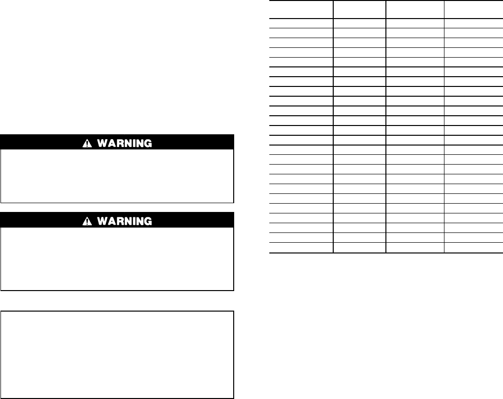
Unit sizes 230-420 are modular units which are shipped
as separate sections (modules A and B). Installation instruc-
tions specific to these units are shipped inside the individual
modules. See Table 1 for a listing of unit sizes and modular
combinations. For modules 230B-315B, follow all general
instructions as noted for unit sizes 080-110. For all remain-
ing modules, follow instructions for unit sizes 130-210.
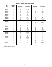
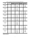
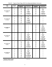
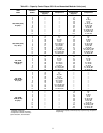
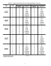
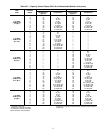
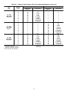
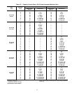
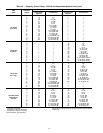
Table 1 — Unit Sizes and Modular Combinations
UNIT MODEL
30GN
NOMINAL
TONS
SECTION A
UNIT 30GN
SECTION B
UNIT 30GN
040 40 — —
045 45 — —
050 50 — —
060 60 — —
070 70 — —
080 80 — —
090 90 — —
100 100 — —
110 110 — —
130 125 — —
150 145 — —
170 160 — —
190 180 — —
210 200 — —
230 220 150 080
245 230 150 090
255 240 150 100
270 260 170 100
290 280 190 110
315 300 210 110
330 325 170 170
360 350 190 190/170*
390 380 210 190
420 400 210 210
*60 Hz units/50 Hz units.
The Flotronic II control system cycles compressor un-
loaders and/or compressors to maintain the selected leaving
fluid temperature set point. It automatically positions the EXV
to maintain the specified refrigerant superheat entering the
compressor cylinders. It also cycles condenser fans on and
off to maintain suitable head pressure for each circuit. Safe-
ties are continuously monitored to prevent the unit from op-
erating under unsafe conditions. A scheduling function, pro-
grammed by the user, controls the unit occupied/unoccupied
schedule. The control also operates a test program that al-
lows the operator to check output signals and ensure com-
ponents are operable.
The control system consists of a processor module (PSIO),
a low-voltage relay module (DSIO-LV), 2 EXVs, an EXV
driver module (DSIO-EXV), a 6-pack relay board, a keypad
and display module (also called HSIO or LID), thermistors,
and transducers to provide inputs to the microprocessor. A
standard options module (SIO) is used to provide additional
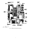
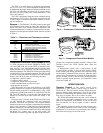
functions. See Fig. 1 for a typical 30GN Control Panel.
MAJOR SYSTEM COMPONENTS
Processor Module —
This module contains the oper-
ating software and controls the operation of the machine. It
continuously monitors information received from the vari-
ous transducers and thermistors and communicates with the
relay modules and 6-pack relay board to increase or de-
crease the active stages of capacity. The processor module
2