


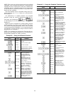
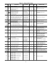

Example 6 — Changing Reset Type
To change type of reset, first log on as shown in
Table 12. Also refer to Set Point Function section, page 38,
for information on entering reset set points using reset
feature.
KEYPAD DISPLAY
COMMENTS
ENTRY RESPONSE
FLD CFG
Field configuration
subfunction of
service function
CSPTYP 0
Scroll past single cooling
set point
CRTYP 0
No reset has been
selected
CRTYP 1
Internally powered 4-20 mA
signal reset is selected
CRTYP 2
Space or outdoor-air
temperature reset is
selected
CRTYP 3
Return fluid temperature
reset is selected
CRTYP 4
Externally powered 4-20 mA
signal reset is selected
CRTYP 0 Reset is deactivated
To use Demand Limit, first enable loadshed, then enter
demand limit set points. See Example 7A. Closing the first
stage demand limit contact puts unit on the first demand limit
level, that is, the unit does not exceed the percentage of ca-
pacity entered as demand limit stage 1. Closing contacts on
second-stage demand limit relay prevents unit from exceed-
ing capacity entered as demand limit stage 2. The demand
limit stage that is set to the lowest demand takes priority if
both demand limit inputs are closed.
The demand limit function must be enabled in order to
function and may be turned off when its operation is not de-
sired. The demand limit relays can, in off condition, remain
connected without affecting machine operation.
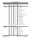
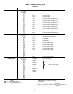
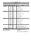
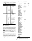
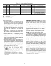
Table 12 — Service Functions
To view and modify configurations, the password must be
entered under the log on subfunction.
SUB- KEYPAD
DISPLAY COMMENT
FUNCTION ENTRY
1 Log On
PASSWORD
Enter Password/
Disable Password
LOGGEDON Logged On
NOTE: Configurations may be modified at this time. When
finished viewing and/or modifying configurations, log out as
follows:
LOGGEDON —
LOG OFF
Disable Password
Protection
EXIT LOG
Logged Off/
Enable Password
Protection
2 Version
VERSION
Software
Information
XXXXXXXX
Version No.
of Software
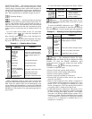
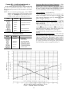
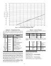
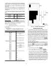
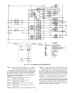
Demand Limit, 4 to 20 mA Signal — The controls can also
accepta4to20mAsignal for load shedding. Input for the
signal are terminals shown below:
Externally powered
Positive lead to J7-5 - 4 In/4 Out Module
Negative lead to J7-6 - 4 In/4 Out Module
Internally powered
Positive lead to J7-6 - 4 In/4 Out Module
Negative lead to J7-7 - 4 In/4 Out Module
See Field Wiring section on page 69 and Fig. 7.
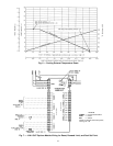
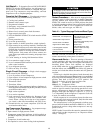
Fig. 8 — 4-20 mA Cooling Temperature Reset
42