


Periods 4 and 5 can be programmed in the same manner,
flagging Thursday and Friday yes for period 4 and Saturday
yes for period 5. For this example, periods 6, 7, and 8
are not used: they should be programmed OCC 00.00,
UNO 00.00.
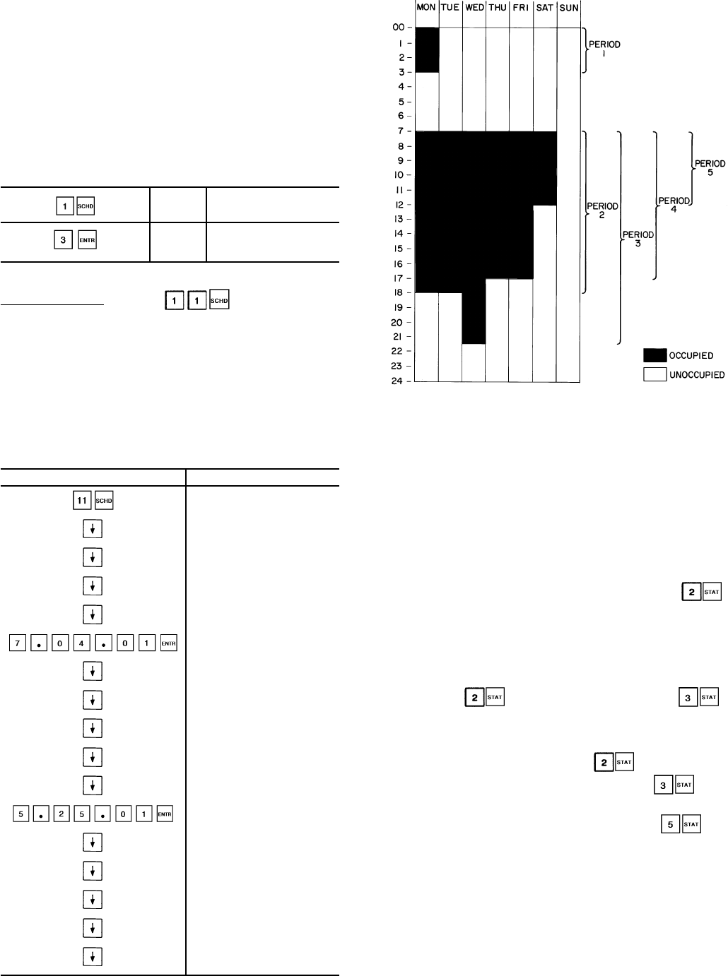
NOTE: When a day is flagged yes for 2 overlapping periods,
occupied time will take precedence over unoccupied time.
Occupied times can overlap in the schedule with no
consequence.
To extend an occupied mode beyond its normal termina-
tion for a one-time schedule override, program as shown
below:
OVRD 0
Override is set for 0. Enter
the number of hours of
override desired
OVRD 3
Unit will now remain in
occupied mode for
an additional 3 hours
Holiday Schedule — Press to schedule up to
30 holiday periods. All holidays are entered with numerical
values. First, the month (01 to 12), then the day (01 to 31),
then the duration of the holiday period in days.
Examples: July 04 is 07.04.01.
Dec 25 - 26 is 12.25.02
If any of the 30 holiday periods are not used, the display
shows NEW.
See Example 10.
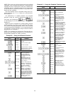
Example 10 — Holiday Schedule Function
ENTER DISPLAY
HOLIDAY
JAN01 02 (Includes Jan 1st
and 2nd)
APR17 01 (Includes April 17th)
MAY21 01(Includes May 21st)
JUL03 01 (Includes July 3rd)
JUL04 01 (Includes July 4th)
SEP07 01 (Includes Sep. 7th)
NOV26 02 (Includes Nov. 26th
and 27th)
DEC24 02 (Includes Dec. 24th
and 25th)
DEC30 02 (Includes Dec. 30th
and 31st)
NEW
MAY25 01 (Includes May 25th)
NEW
NEW
NEW
NEW
NEW (30TH HOLIDAY)
NEW indicates a holiday that has not been assigned yet.
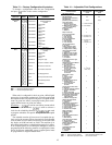
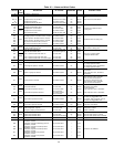
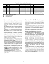
TROUBLESHOOTING
The Flotronic™ II control has many features to aid the
technicians in troubleshooting a Flotronic II Chiller. By us-
ing the keypad and display module and the status function,
actual operating conditions of the chiller are displayed while
unit is running. Test function allows proper operation of com-
pressors, compressor unloaders, fans, EXVs and other com-
ponents to be checked while chiller is stopped. Service func-
tion displays how configurable items are configured. If an
operating fault is detected, an alarm is generated and an
alarm code(s) is displayed under the subfunction ,
along with an explanation of the fault. Up to 10 current alarm
codes are stored under this subfunction. For checking spe-
cific items, see Table 9.
Checking Display Codes — To determine how ma-
chine has been programmed to operate, check diagnostic
information ( ) and operating mode displays ( ).
If no display appears, follow procedures in Control Modules
section on page 63. If display is working, continue as
follows:
1. Note all alarm codes displayed, .
2. Note all operating mode codes displayed, .
3. Note leaving chilled water temperature set point in ef-
fect and current leaving water temperature, .
If machine is running, compare the ‘‘in effect’’ leaving
water temperature set point with current water tempera-
ture. Remember, if reset is in effect, the values may be
different because machine is operating to the modified chilled
water set point. If current temperature is equal to set point,
but set point is not the one desired, remember that if dual
set point has been selected in the schedule function, there
are 2 set points to which the machine can be operating.
Check the programming of schedule function to see if oc-
cupied or unoccupied set point should be in effect.
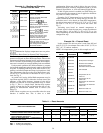
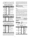
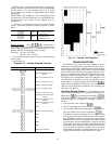
Fig. 10 — Sample Time Schedule
47