


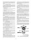
vapor). To control refrigerant flow for different operating con-
ditions, sleeve moves up and down over orifice, thereby chang-
ing orifice size. Sleeve is moved by a linear stepper motor.
Stepper motor moves in increments and is controlled di-
rectly by the processor module. As stepper motor rotates,
motion is transferred into linear movement by lead screw.
Through stepper motor and lead screws, 1500 discrete steps
of motion are obtained. The large number of steps and long
stroke result in very accurate control of refrigerant flow.
The subfunction shows EXV valve position as
a percent of full open. Position should change constantly while
unit operates. If a valve stops moving for any reason (me-
chanical or electrical) other than a processor or thermistor
failure, the processor continues to attempt to open or close
the valve to correct the superheat. Once the calculated valve
position reaches 120 (fully closed) or 1500 (fully open), it
remains there. If EXV position reading remains at 120 or
1500, and the thermistors and pressure transducers are read-
ing correctly, the EXV is not moving. Follow EXV checkout
procedure below to determine cause.
The EXV is also used to limit cooler suction temperature
to 50 F (10 C). This makes it possible for chiller to start at
higher cooler fluid temperatures without overloading com-
pressor. This is commonly referred to as MOP (maximum
operating pressure), and serves as a load limiting device to
prevent compressor motor overloading. This MOP or load
limiting feature enables the 30G Flotronic™ II chillers to
operate with up to 95 F (35 C) entering fluid temperatures
during start-up and subsequent pull-down.
CHECKOUT PROCEDURE — Follow steps below to di-
agnose and correct EXV problems.
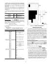
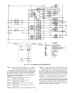
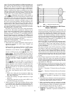
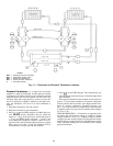
1. Check EXV driver outputs. Check EXV output signals at
appropriate terminals on EXV driver module (see
Fig. 13) as follows:
Connect positive test lead to terminal 1 on EXV driver.
Set meter for approximately 20 vdc. Enter outputs
subfunction of test function by pressing , then
advance to EXVA test by pressing 10 times. Press
. The driver should drive the circuit A
EXV fully open. During next several seconds connect nega-
tive test lead to pins 2, 3, 4, and 5 in succession. Voltage
should rise and fall at each pin. If it remains constant at
a voltage or at zero v, remove connector to valve and
recheck.
Press to close circuit A EXV. If a problem still
exists, replace EXV driver module. If voltage reading is
correct, expansion valve should be checked. Next, test
EXVB. Connect positive test lead to pin 7 and the nega-
tive test lead to pin 8, 9, 10, and 11 in succession during
EXVB test.
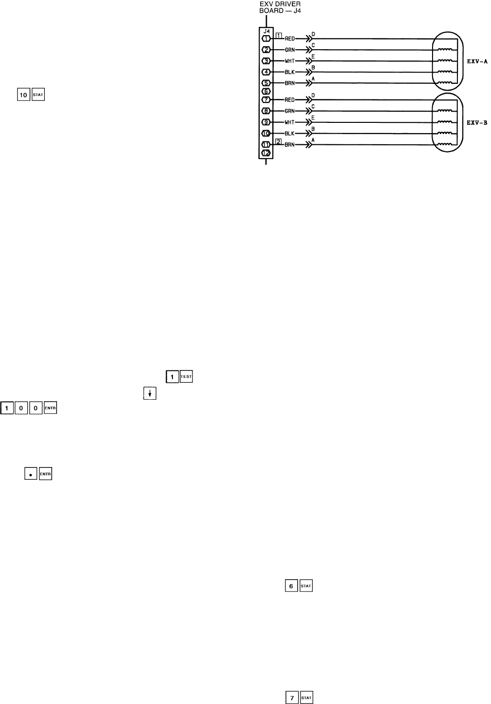
2. Check EXV wiring. Check wiring to electronic expan-
sion valves from terminal strip on EXV driver. See
Fig. 13.
a. Check color coding and wire connections. Make sure
they are connected to correct terminals at driver and
EXV plug connections.
b. Check for continuity and tight connection at all pin
terminals.
c. Check plug connections at driver and at EXVs to be
sure EXV cables are not crossed.
3. Check resistance of EXV motor windings. Remove plug
at J4 terminal strip and check resistance between com-
mon lead (red wire, terminal D) and remaining leads, A,
B, C, and E (see Fig. 13). Resistance should be
25 ohms Ϯ 2 ohms.
Control of valve is by microprocessor. A thermistor and
a pressure transducer located in lead compressor are used
to determine superheat. The thermistor measures tem-
perature of the superheated gas entering the compressor
cylinders. The pressure transducer measures refrigerant
pressure in the suction manifold. The microprocessor con-
verts pressure reading to a saturation temperature. The
difference between temperature of superheated gas and
saturation temperature is the superheat.
Because the EXVs are controlled by the processor mod-
ule, it is possible to track valve position. During initial
start-up, EXV is fully closed. After start-up, valve posi-
tion is tracked by processor by constantly observing amount
of valve movement.
The processor keeps track of EXV position by counting
the number of open and closed steps it has sent to each
valve. It has no direct physical feedback of valve posi-
tion. Whenever unit is switched from STOP to RUN po-
sition, both valves are initialized, allowing the processor
to send enough closing pulses to the valve to move it from
fully open to fully closed, then reset the position counter
to zero.
4. The EXV test can be used to drive EXV to any desired
position. When EXV opens, the metering slots begin to
provide enough refrigerant for operation at step 120. This
is fully closed position when circuit is operating. The fully
open position is 1500 steps.
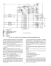
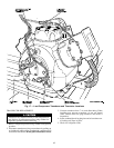
5. Check thermistors and pressure transducers that control
EXV. Check thermistors and pressure transducers that con-
trol processor output voltage pulses to EXVs. See Fig. 14
for locations.
Circuit A — Thermistor T7, Suction Pressure Transducer
SPTA
Circuit B — Thermistor T8, Suction Pressure Transducer
SPTB
a. Use temperature subfunction of the status function
( ) to determine if thermistors are reading
correctly.
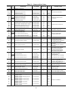
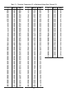
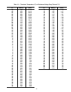
b. Check thermistor calibration at known temperature by
measuring actual resistance and comparing value mea-
sured with values listed in Tables 17 and 18.
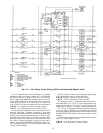
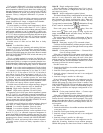
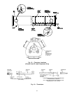
c. Make sure thermistor leads are connected to proper
pin terminals at J7 terminal strip on processor module
and that thermistor probes are located in proper posi-
tion in refrigerant circuit. See Fig. 15 and 16.
d. Use the pressure subfunction of the Status function
( ) to determine if pressure transducers are
EXV — Electronic Expansion Valve
Fig. 13 — EXV Cable Connections to EXV Driver
Module, DSIO (EXV)
56