


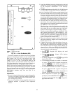


REPLACING DEFECTIVE
PROCESSOR MODULE
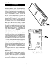
The replacement part number is printed on a small label
on the front of the PSIO module. The model and serial num-
bers are printed on the unit nameplate located on an exterior
corner post. The proper software and unit configuration data
is factory installed by Carrier in the replacement module.
Therefore, when ordering a replacement processor module
(PSIO), specify complete replacement part number, full unit
model number, and serial number. If these numbers are not
provided, the replacement module order is configured in-
stead as a generic Flotronic II replacement module. This re-
quires reconfiguration of the module by the installer.
Electrical shock can cause personal injury. Disconnect
all electrical power before servicing.
Installation
1. Verify the existing PSIO module is defective by using
the procedure described in the Control Modules section
on page 63.
2. Refer to Start-Up Checklist for Flotronic II Chiller Sys-
tems (completed at time of original start-up) found in
job folder. This information is needed later in this
procedure. If checklist does not exist, fill out the
and configuration code sections on a new check-
list. Tailor the various options and configurations as needed
for this particular installation.
3. Check that all power to unit is off. Carefully disconnect
all wires from defective module by unplugging the 6 con-
nectors. It is not necessary to remove any of the indi-
vidual wires from the connectors. Remove the green ground
wire.
4. Remove defective PSIO by removing its mounting screws
with a Phillips screwdriver, and removing the module
from the control box. Save the screws for later use.
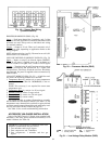
5. Use a small screwdriver to set address switches S1 and
S2 on the new PSIO module to exactly match the set-
tings on the defective module.
6. Package the defective module in the carton of the new
module for return to Carrier.
7. Mount the new module in the unit control box using a
Phillips screwdriver and the screws saved in Step 4 above.
8. Reinstall all 6 wire connectors and the green ground wire.
9. Carefully check all wiring connections before restoring
power.
10. Verify the LOCAL/ENABLE-STOP-CCN switch is in
STOP position.
11. Restore control power. Verify the red and green lights
on top of PSIO and front of each DSIO module respond
as described in Control Modules section on page 63. The
keypad and display module should also begin its rotat-
ing display.
12. Using the keypad and display module, press
to verify that the software version number matches the
ER (engineering requirement) number shown on the PSIO
label.
13. Press to verify that the 7 factory configuration
codes (CODE 1 through CODE 7) exactly match the codes
listed for this unit model on the component arrangement
label diagram on the control box door. If they are dif-
ferent or are all zeros, reenter the 7 codes. If any changes
are required, the PSIO display becomes blank and
reconfigures itself after pressing the key while dis-
playing CODE 7. The display returns in approximately
15 seconds.
NOTE: Codes with leading zeros in the configuration
will be displayed starting with the first number greater
than zero.
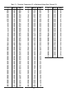
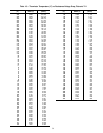
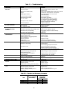
14. Press to verify each item is configured as needed
for this particular installation. Table 14 shows the fac-
tory configuration code default settings. Table 14 also
shows the service replacement code default settings which
are used if no model number was specified when order-
ing the replacement PSIO module. It is strongly sug-
gested that the Start-Up Checklist for Flotronic II Chiller
Systems (completed at time of original start-up) be used
at this time to verify and/or reprogram the various op-
tions and configurations required for this job.
15. Press to verify that the 2 field configuration
codes (codes 8 and 9) match exactly the codes listed on
the label diagram on the control box door. If they are
different, or are all zeros, reenter the 2 codes.
16. After completing the configuration steps outlined above,
restore main power and perform a unit test as de-
scribed in and sections on page 38.
17. Complete this procedure and restore chiller to normal
operation by returning the LOCAL/ENABLE-STOP-
CCN switch to desired position.
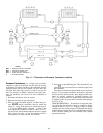
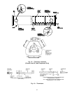
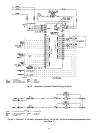
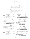
TB — Terminal Block
Fig. 34 — Remote Alarm
CWP1 — Chilled Water (Fluid) Pump Interlock
CWFS — Chilled Water (Fluid) Flow Switch (not required — low flow
protection is provided by Flotronic™ II controls)
TB — Terminal Block
Fig. 35 — Interlocks
70