


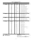
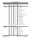
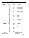
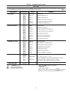

Table 10 — Operational and Mode Display Codes
The operating modes are displayed by name or code num-
ber, to indicate the operating status of the unit at a given
time. The modes are:
CODE DESCRIPTION
LOCAL OFF
Unit is off. LOCAL/ENABLE-STOP-CCN switch is in
OFF position,or LOCAL/ENABLE-STOP-CCNswitch
may be in LOCAL position with external ON/OFF
switch in OFF position.
CCN OFF
Unit is off due to CCN network command. LOCAL/
ENABLE-STOP-CCN switch is in CCN position.
CLOCK OFF
Unit is off due to internal clock schedule. LOCAL/
ENABLE-STOP-CCN switch is in LOCAL position.
LOCAL ON
Unit is on. LOCAL/ENABLE-STOP-CCN switch is in
LOCAL position. If external ON/OFF switch is used,
it will be in ON position.
CCN ON
Unit is on due to CCN command. LOCAL/ENABLE-
STOP-CCN switch is in CCN position.
CLOCK ON
Unit is on due to internal clock schedule or occu-
pied override function. LOCAL/ENABLE-STOP-
CCN switch is in LOCAL/ENABLE position.
MODE 7
Dual set point is in effect. In this mode, unit contin-
ues to run in unoccupied condition, but leaving fluid
set point is automatically increased to a higher level
(CSP2 set point is in SET function).
MODE 8
Temperature reset is in effect. In this mode, unit is
using temperature reset to adjust leaving fluid set
point upward, and unit is currently controlling to the
modified setpoint. Theset pointcan bemodified based
on returnfluid, outdoor-air temperature,or space tem-
perature.
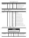
MODE 9
Demand limit is in effect. This indicates that ca-
pacity of unit isbeing limited by demand limit control
option. Because of this limitation, unit may not
be able to produce the desired leaving fluid
temperature.
MODE 10
Flotronic™ System Manager(FSM) is controlling the
chiller.
MODE 11 Not applicable.
MODE 12
Ramp load(pulldown) limiting isin effect.In this mode,
the rate atwhich leaving fluidtemperature is dropped
is limited to a predetermined value to prevent com-
pressor overloading. See CRAMP set point in the
SET function in Table 9. The pulldown limit can be
modified, if desired, to any rate from .2 F to 2 F
(.1° to 1° C)/minute.
MODE 13
Timed override is in effect. This isa1to4hour tem-
porary override of the programmed schedule, forc-
ing unit to occupied mode. Override can be imple-
mented with unit under LOCAL/ENABLE or CCN
control. Override expires after each use.
MODE 14
Low coolersuction protection isin effect. Inthis mode,
circuit capacity is not allowed to increase if cooler
saturated suction temperature is 20° F (11° C) for
fluid or 30° F (16° C)for brine or more below leaving
fluid temperature, and saturated suction tempera-
ture is less than 32 F (0° C). If these conditions per-
sist beyond 10minutes, circuit is shutdown and fault
code 44 or 45 is displayed.
MODE 15 Water System Manager is controlling the chiller.
MODE 16 Slow change override is in effect.
MODE 17 X minute off-to-on delay is in effect.
MODE 18 Low suction superheat protection is in effect.
CCN — Carrier Comfort Network
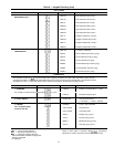
(Set Point) — This subfunction displays leaving
fluid temperature and leaving chilled fluid set point. If unit
is programmed for dual set point, the chilled fluid set point
currently in effect (either occupied or unoccupied) is
displayed. If reset is in effect, the unit operates to the modi-
fied chilled fluid set point. This means the leaving fluid tem-
perature may not equal the chilled fluid set point. The
modified chilled fluid set point can also be displayed in the
Status function. To enter the set point subfunction,
press and press to display the set point fol-
lowed by the modified leaving chilled fluid set point and ac-
tual control temperature.
(Temperature) — The temperature subfunction dis-
plays the readings at temperature sensing thermistors.
To read a temperature, enter , then scroll to de-
sired temperature using the key. See Table 9 for the
order of readouts. This subfunction also displays the satu-
rated refrigerant temperatures corresponding to the suction
and discharge pressures measured by the compressor
transducers.
(Pressure) — This subfunction displays suction,
discharge, and net oil pressure at lead compressor of each
circuit of unit.
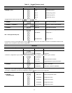
(Analog Inputs) — This subfunction displays
analog inputs, if any. Press , then press . The
transducer supply voltage, 4-20 mA reset signal can be dis-
played. This is useful for problem diagnosis prior to using
the test function.
(Discrete Inputs) — This subfunction displays sta-
tus (open/closed) of discrete input switch where applicable.
Status of dual set point switch and demand limit switches 1
and 2 can be displayed. This is useful for problem diagnosis
prior to using the test function.
(Outputs) — This function displays on/off sta-
tus of alarm relay, all fan relays, and chilled water pump
relay. It also displays on/off status of compressor unloaders
(if used). The position of each EXV (in percent open) can be
displayed.
TEST FUNCTION — The test function operates the diag-
nostic program. To initiate test function, the LOCAL/
ENABLE-STOP-CCN switch must be in STOP position.
To reach a particular test, press its subfunction number,
then scroll to desired test by pressing . Press to
start a test. Press or or to terminate or exit a
test. Pressing the key after a test has started advances
system to next test, whether current test is operating or has
timed out. Once in the next step, you may start
test by pressing or advance past it by pressing .
While the unit is in test, you may leave test function and
access another display or function by pressing appropriate
keys. However, a component that is operating when an-
other function is accessed remains operating. You must
re-enter test function and press to shut down the com-
ponent. Components with a timed operating limit time out
normally even if another function is accessed.
37