


Keypad entry allows the operator to make the
following checks by using :
• LID display check. Proper display is 8.8.8.8.8.8.8.8.
• Operation of alarm relay.
• Operation of condenser fans.
• Operation of chilled fluid pump.
• Operation of liquid line solenoids.
• Operation of the hot gas bypass relays.
• Operation of EXVs. To drive EXV fully open, enter
(100% open). To drive EXV fully closed, en-
ter (0% open).
• Operation of each remote alarm.
• Operation of Motormaster signals.
Keypad entry accesses the compressor and
compressor unloader operational tests.
During compressor operational tests, compressor starts
and runs for 10 seconds. Compressor service valves must
be open. Energize crankcase heaters 24 hours prior to
performing compressor tests.
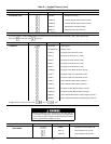
Since test function checks only certain outputs, it is good
practice to also check all inputs and outputs accessible
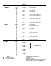
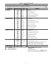
through the status function. These are located at ,
, and (see Table 9). If keypad is not used
for 10 minutes, unit automatically leaves test function and
resumes rotating display. See Example 3.
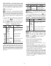
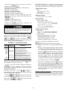
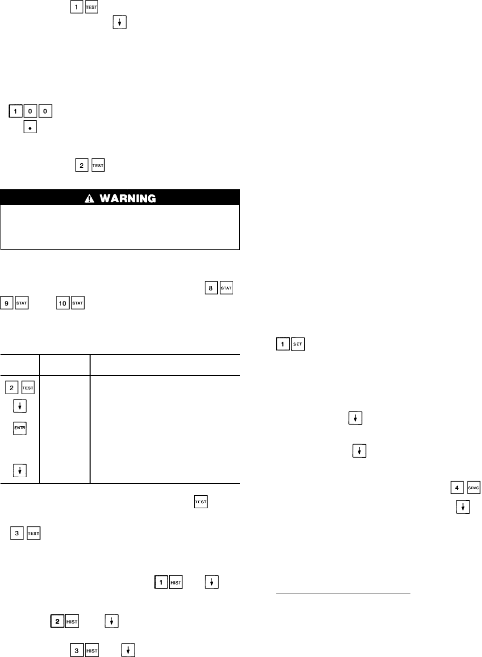
Example 3 — Using Test Function
KEYPAD DISPLAY
COMMENTS
ENTRY RESPONSE
COMP Factory/field test of compressors
subfunction of test function
CPA 1 OFF Circuit A, Compressor 1A test
CPA 1 ON Pressing ENTR starts the test:
when the compressor should be running
the display shows CPA1 on
CPA 1 OFF If the test is allowed to time out (10 sec-
onds) the display will show CPA1 off
CPA 2 OFF Pressing thedown arrow keyadvances the
system to Circuit A, compressor 2 test
NOTE: Once a compressor has been run using the function,
it is not allowed to run again for 30 seconds.
accesses the transducer calibration subfunction.
All transducers must be calibrated in order for the unit to
operate. Refer to Pressure Transducers section on page 60
for calibration procedure.
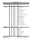
HISTORY FUNCTION — Pressing and dis-
plays total unit run time, total run time for each circuit, and
total run time for each compressor.
Pressing and displays total unit starts, the
total starts for each circuit, and total starts for each com-
pressor. Pressing and displays the last 10 alarms
along with a description of each alarm.
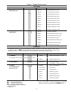
SET POINT FUNCTION — Set points are entered through
the keypad. Set points can be changed within the upper and
lower limits, which are fixed. The ranges are listed below.
Chilled Fluid Set Point
Water:
38 to 86 F (3.3 to 30 C)
Medium Brine:
14 to 86 F (–10 to 30 C)
Pulldown Set Point
0.2 to 2.0 F (0.11 to 1.1 C)/min.
Reset Set Points
Maximum Reset Range:
–30° to 30° F (–17° to 17° C)
External Temperature Reset –40 to 240 F
(–40 to 118 C)
Chiller Fluid ⌬T: 0° to 15° F
(0° to 8° C)
External Signal Reset 4 to 20 mA
Demand Limit Set Points
Switch Input:
Step1—0to100% Capacity Reduction
Step2—0to100% Capacity Reduction
External Signal:
Maximum Demand Limit 4 to 20 mA
Minimum Demand Limit 4 to 20 mA
Loadshed Demand Delta: 0 to 60%
Maximum Loadshed Time: 0 to 120 min.
Set points are grouped in subfunctions as follows:
Subfunction displays chiller fluid set points.
a. The first value shown is the occupied chilled fluid set
point.
b. The next value displayed depends on how the sched-
ule function has been programmed. (See pages 44-
47.) If dual set point has been selected, the next set
point after has been pressed is the second chilled
fluid set point. If single set point or inactive sched-
ule has been selected in the schedule function,
then when is pressed, the display shows the
head pressure set points, one for each circuit. These
are utilized only if the set point controlled method of
head pressure control is selected in .
c. The final value displayed when the is pressed
is the cooling ramp loading rate. This is the maximum
rate at which the leaving chilled fluid is allowed to
drop, and can be field set from 0.2 to 2.0 F (.11° to
1.1° C)/minute. This value is not displayed unless the
function is enabled (see Adjustable Field Configura-
tions on page 44).
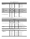
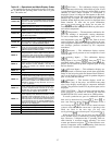
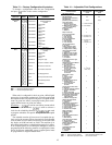
Reading and Changing Set Points — Example 4 shows how
to read and change the chilled fluid set point. Other set points
can be changed by following the same procedure. Refer to
Table 9 for the sequence of display of set points in each sub-
function.
38