


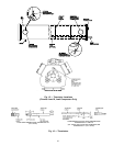
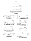

PROCESSOR MODULE (PSIO) (Fig. 20)
Inputs — Each input channel has 3 terminals; only 2 of the
terminals are used.Application of machine determines which
terminals are used. Always refer to individual unit wiring
for terminal numbers.
Outputs — Output is 24 vdc. There are 3 terminals, only 2
of which are used, depending on application. Refer to unit
wiring diagram.
NOTE: Address switches (see Fig. 20) must be set at 01 (dif-
ferent when CCN connected).
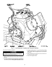
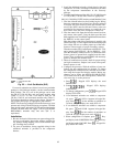
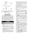
LOW VOLTAGE RELAY MODULE (DSIO-LV) (Fig. 21)
Inputs — Inputs on strip J3 are discrete inputs (ON/OFF).
When 24-vac power is applied across the 2 terminals in a
channel it reads as on signal. Zero v reads as an off signal.
Outputs — Terminal strips J4 and J5 are internal relays whose
coils are powered-up and powered-off by a signal from
microprocessor. The relays switch the circuit to which they
are connected. No power is supplied to these connections by
DSIO module.
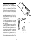
4 IN/4 OUT MODULE (SIO) (Fig. 22) — 4 In/4 Out mod-
ule allows the following features to be utilized:
1. Temperature Reset by outdoor air or space temperature.
A remote thermistor (Part No. 30GB660002) is also re-
quired.
NOTE: This accessory is not required for return water
temperature reset.
2. Temperature Reset by remote 4 to 20 mA signal.
3. Demand Limit by remote 2-stage switch.
4. Demand Limit by remote 4 to 20 mA signal
5. Dual Set Point by remote switch.
The options module is standard. Remember to reconfig-
ure the chiller for each feature selected (see Table 14). For
temperature reset, demand limit, and dual set point, desired
set points must be entered through keypad and display mod-
ule (see Set Point Function section on page 38).
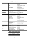
See Table 19 for overall troubleshooting information.
ACCESSORY UNLOADER INSTALLATION
Some of the 30G Flotronic™ II units come standard with
unloader(s), and many permit additional unloader(s) to be
added if desired. See Table 20.
IMPORTANT: The following combinationsARE NOT
permitted (combinations are per circuit):
1. Two unloaders and hot gas bypass
2. Four compressors and 2 unloaders.
3. Four compressors, 1 unloader, and hot gas
bypass.
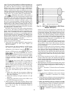
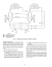
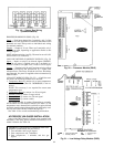
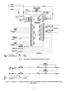
Fig. 19 — Sensor Bus Wiring
(Communications)
PWR — Power
Fig. 20 — Processor Module (PSIO)
LEGEND
COMM — Communications Bus
NC — Normally Closed
NO — Normally Open
PWR — Power
Fig. 21 — Low-Voltage Relay Module (DSIO)
64