


Head Pressure Control
EXV UNITS (All 30GN units except 040 and 045 with op-
tional brine) — The microprocessor controls the condenser
fans in order to maintain the lowest condensing temperature
possible, thus the highest unit efficiency. Instead of using the
conventional head pressure control methods, the fans are con-
trolled by the position of the EXV and suction superheat.
As the condensing temperature drops, the EXV opens to
maintain the proper suction superheat. Once the EXV is fully
open, if the condensing temperature continues to drop, the
suction superheat begins to rise. Once the suction superheat
is greater than 40 F (22.2 C), a fan stage is removed after
2 minutes.
As the condensing temperature rises, the EXV closes to
maintain the proper suction superheat. Once the EXV has
closed to 39.5% open (600 steps open), a fan stage is added
after 2 minutes.
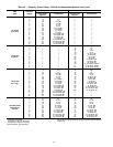
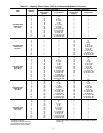
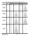
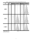
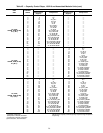
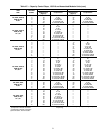
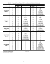
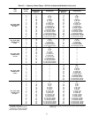
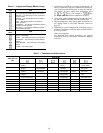
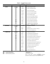
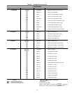
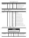
During start-up, all the condenser fans are started when
the condensing temperature reaches 95 F (35 C) to prevent
excessive discharge pressure during pulldown. See Table 5
for condenser fan sequence of operation.
For low-ambient operation, the lead fan in each circuit can
be equipped with the optional or accessory Motormaster
III head pressure controller. This control has its own sensor
which is mounted on a return bend in the liquid portion of
the condenser. It will vary the fan speed to maintain a satu-
rated condensing temperature of 100 F. The controls auto-
matically default to condensing temperature control during
this first stage of condenser-fan operation. When subsequent
fan stages start, the controls revert to EXV fan control.
TXV UNITS (30GN040,045 with optional brine only) —
Head pressure control is based on set point control. The micro-
processor stages the condenser fans to maintain the set point
temperature specified by the controller.
Pumpout
EXV UNITS — When the lead compressor in each circuit
is started or stopped, that circuit goes through a pumpout
cycle to purge the cooler and refrigerant suction lines of
refrigerant.
The pumpout cycle starts immediately upon starting the
lead compressor and continues until the saturated suction tem-
perature is 10° F (5.6° C) below the saturated suction tem-
perature at start-up, is 10° F (5.6° C) below the cooler leav-
ing fluid temperature, or reaches a saturated suction temperature
of –15 F (–26 C). No pumpout is necessary if the saturated
suction temperature is below –15 F (–26 C). At this point,
the EXV starts to open and continues to open gradually to
provide a controlled start-up to prevent liquid flood-back to
the compressor.
At shutdown, the pumpout cycle continues until the satu-
rated suction temperature for that circuit is 10° F (5.5° C)
below the saturated suction temperature when pumpout is
initiated, or saturated suction temperature reaches –15 F
(–26 C). At that point, the compressor shuts down and the
EXV continues to move until fully closed.
TXV UNITS — Pumpout is based on timed pumpout. On a
command for start-up, the lead compressor starts. After
10 seconds, the liquid line solenoid opens. At shutdown, the
liquid line solenoid closes, and the lead compressor contin-
ues to run for 10 seconds before stopping.
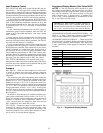
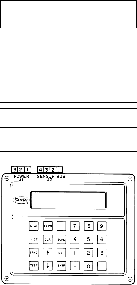
Keypad and Display Module (Also Called HSIO
or LID) —
The only function of this module is to allow
the operator to communicate with the processor. It is used to
enter configurations and set points and to read data, perform
tests, and set schedules. This device consists of a keypad
with 6 function keys, 5 operative keys, 12 numeric keys
(0 to 9, •, and -), and an alphanumeric, 8-character LCD. See
Fig. 4. See Table 6 for key usage.
IMPORTANT: When entering multiple character in-
puts beginning with a zero, a decimal point must be
entered in place of the first zero. When entering an in-
put of zero, only the decimal point need be entered.
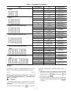
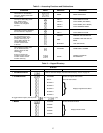
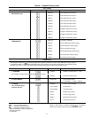
ACCESSING FUNCTIONS AND SUBFUNCTIONS — See
Tables6-8.Table 7 shows the 6 functions (identified by
name) and the subfunctions (identified by number).
AUTOMATIC DEFAULT DISPLAY — When keypad has
not been used for 10 minutes, display automatically switches
to the rotating automatic default display. This display has
7 parts, listed below, which appear in continuous rotating
sequence.
DISPLAY EXPANSION
TUE 15:45 TODAY IS TUE, TIME IS 15:45 (3:45 PM)
LOCAL ON UNIT IN LOCAL MODE
CLOCK ON UNIT IS ON VIA CLOCK SCHEDULE
8 MODE TEMPERATURE RESET IN EFFECT
COOL 1 NUMBER OF STAGES IS 1
2 ALARMS THERE ARE 2 ALARMS
3 MINS
3 MINUTES REMAINING IN THE OFF-TO-ON
TIME DELAY
Fig. 4 — Keypad and Display Module
24