


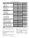
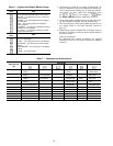
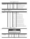

Table 6 — Keypad and Display Module Usage
FUNCTION
KEYS
USE
STATUS — For displaying diagnostic codes and
current operating information about the machine.
HISTORY — For displaying run time, cycles and
previous alarms.
SERVICE — For entering specific unit configura-
tion information.
TEST — For checking inputs and outputs for
proper operation.
SCHEDULE — For entering occupied/unoccupied
schedules for unit operation.
SET POINT — For entering operating set points
and day/time information.
OPERATIVE
KEYS
USE
EXPAND — For displaying a non-abbreviated ex-
pansion of the display.
CLEAR — For clearing the screen of all displays.
UP ARROW — For returning to previous display
position.
DOWN ARROW — For advancing to next display
position.
ENTER — For entering data.
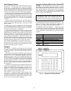
3. All functions are made up of a group of subfunctions. To
enter a subfunction, first press subfunction number de-
sired. Then press the function key in which the subfunc-
tion resides. To move within that subfunction, press
the or arrow. For example, a enters
the Temperature Information subfunction.
4. At any time, another subfunction may be entered by press-
ing the subfunction number, then the function key.
5. Prior to starting unit, check leaving fluid set point for cor-
rect setting. Refer to Set Point Function section on
page 38.
6. Depending on system configuration, all displays may not
be shown. All displays are shown unless marked with the
following symbol:
†Must be configured.
For additional unit start-up procedures, see separate
Installation, Start-Up, and Service Instructions supplied
with unit.
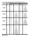
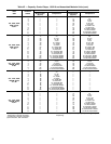
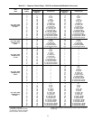
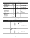
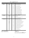
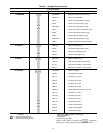
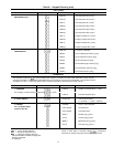
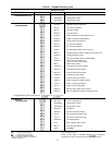
Table 7 — Functions and Subfunctions
SUBFUNCTION
NO.
FUNCTIONS
Status Test Schedule Service History Set Point
1 Automatic
Display
Outputs Override Log On and
Log Off
Run Time Set Points
(Chiller Fluid)
2 Alarm
Display
Compressors
and Unloaders
Clock Select Version
(Software)
Starts Reset
Set Points
3 Mode (Operating)
Display
Calibrate
Transducers
Period 1 Factory
Configuration
Alarm
History
Demand Limit
Set Points
4 Capacity
Stages
— Period 2 Field
Configuration
— Date and
Time
5 Set Points
(Current Operating)
— Period 3 Service
Configuration
— Leaving Chiller
Fluid Alert Limit
6 Temperatures — Period 4 — — —
7 Pressures — Period 5 — — —
8 Analog Inputs — Period 6 — — —
9 Discrete Inputs — Period 7 — — —
10 Outputs — Period 8 — — —
11 — — HOLIDAYS — — —
26