


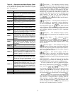
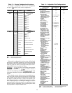
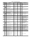
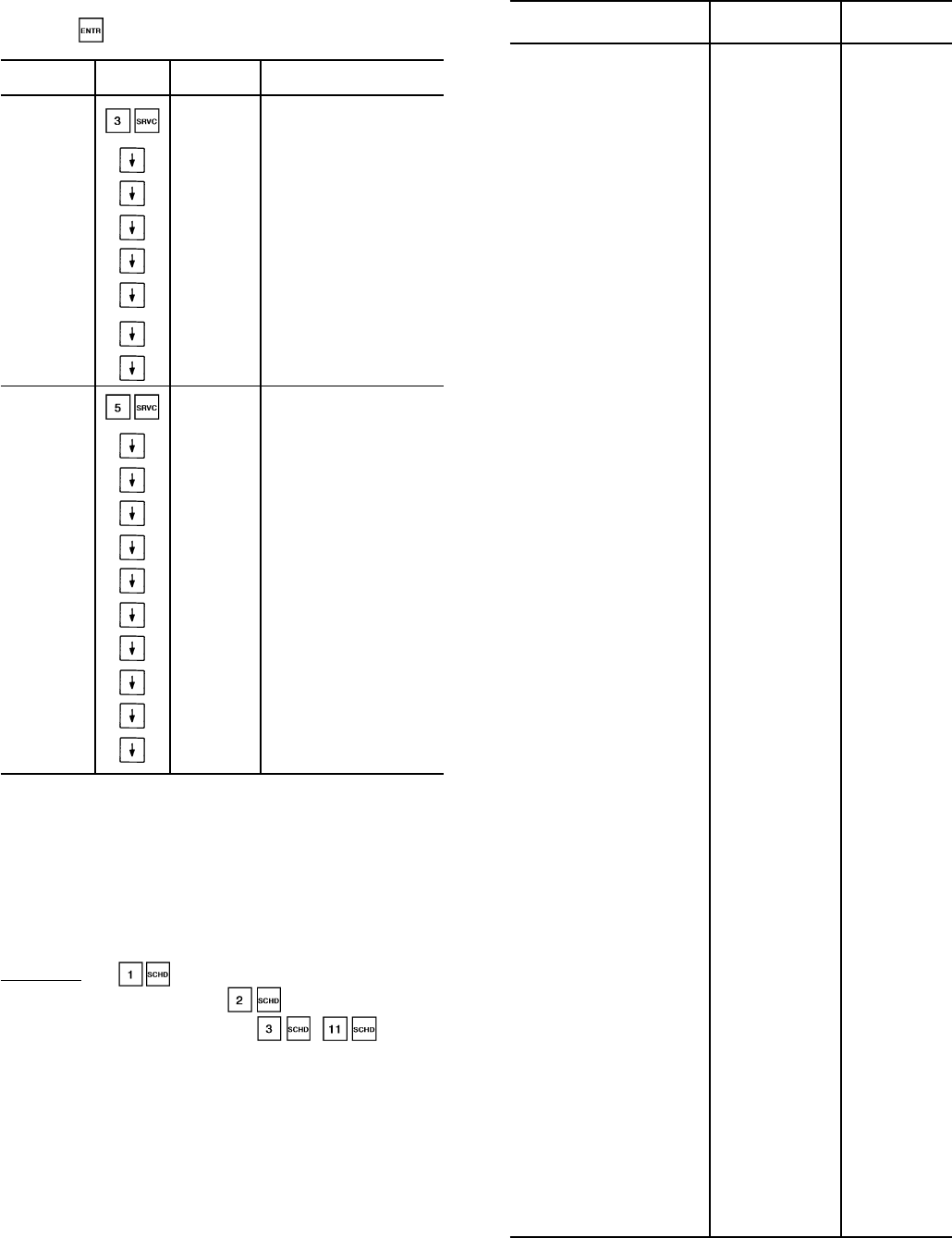
Table 13 — Factory Configuration Keystrokes
To change a configuration enter the new configuration
and press while on the correct configuration.
SUB- KEYPAD
DISPLAY COMMENTS
FUNCTION ENTRY
3 FACTORY
CFG
FACT CFG
FACTORY
CONFIGURATION
CODES
XXXXXXXX
Configuration
Code 1
XXXXXXXX
Configuration
Code 2
XXXXXXXX
Configuration
Code 3
XXXXXXXX
Configuration
Code 4
XXXXXXXX
Configuration
Code 5
XXXXXXXX
Configuration
Code 6
XXXXXXXX
Configuration
Code 7
5 SERVICE
CFG
SRV CFG
SERVICE
CONFIGURATION
CODES
XXXXXXXX
Configuration
Code 8
XXXXXXXX
Configuration
Code 9
REFRIG X Refrigerant Type
TDTYPE X Pressure Transducer Select
OPS X Oil Pressure Set Point
LPS X Low Pressure Set Point
FANTYP X Fan Staging Select
SH X EXV Superheat Set Point
MOP X EXV MOP Superheat
ZM X Z Multiplier
LEGEND
MOP — Maximum Operating Pressure
EXV — Electronic Expansion Valve
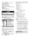
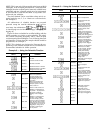
When unit is configured for dual set point, chilled liquid
pump relay is energized continuously, in both occupied and
unoccupied modes. Occupied mode places occupied chilled
water set point into effect; unoccupied mode places unoc-
cupied chilled water set point into effect.
Scheduling — is used to override any current sched-
ule in effect (for 0-4 hours). is used to activate a
clock for the scheduling function. - are used
to program schedules for specific occupied and unoccupied
periods.
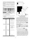
The schedule consists of from one to 8 occupied time pe-
riods, set by the operator. These time periods can be flagged
to be in effect or not in effect on each day of the week. The
day begins at 00.00 and ends at 24.00. The machine is in
unoccupied mode unless a scheduled time period is in effect.
If an occupied period is to extend past midnight, it must be
programmed in the following manner: occupied period must
end at 24:00 hours (midnight); a new occupied period must
be programmed to begin at 00:00 hours.
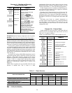
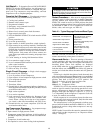
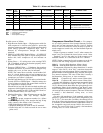
Table 14 — Adjustable Field Configurations
FIELD CONFIGURATION
ITEM AND CODES
FACTORY SERVICE
CONFIGURATION REPLACEMENT
CODE CODE
CCN element address
(Entered by CCN Technician)
001 001
CCN Bus Number
(Entered by CCN Technician)
000 000
CCN Baud Rate
(Entered by CCN Technician)
9600 9600
Cooler Fluid Select
1 = Water (38 to 70 F
[3.3 to 21 C] Set Point)
2 = Medium Brine (15 to 70 F
[–9 to 21 C] Set Point)
1 = Standard Models
2 = Brine Models
1
Display Unit Select
0 = English
1 = Metric SI
00
Delay at Power Up 00
No. Circuit A Unloaders
0 = No Unloaders
1 = One Unloader
2 = Two Unloaders
0 = 30GN190-210*
1 = 30GN040-170*
0
No. Circuit B Unloaders
0 = No Unloaders
1 = One Unloader
2 = Two Unloaders
0 = 30GN040-070,
190-210*
1 = 30GN080-170*
0
Hot Gas Bypass Select
0 = No Valve
00
Loading Sequence Select
1 = Equal Circuit Loading
2 = Staged Circuit Loading
11
Lead/Lag Sequence Select
1 = Automatic
2 = Manual, Circuit A Leads
3 = Manual, Circuit B Leads
11
Oil Pressure Switch Select
0 = Not Used
1 = Air Cooled
00
Head Pressure Control Type
0 = Not Used
1 = Air Cooled
10
Head Pressure Control Method
1 = EXV Controlled
2 = Set Point Control for
Both Circuits
3 = Set Point Control for
Circuit A; EXV Control
for Circuit B
4 = Set Point Control for
Circuit B; EXV Control
for Circuit A
1
2 = 040,045
Brine Units
1
Motormasterா Select
0 = None
2 = Indirect Control
00
Cooling Set Point
Control Select
0 = Single Set Point Control
1 = External Switch
Controlled Set Point
2 = Clock Controlled
Set Point
00
Cooling Reset Control Select
0 = No Reset
1 = 4-20 mA, Internally Powered
2 = External Temperature
Reset
3 = Return Fluid Reset
4 = 4-20 mA, Externally Powered
00
External Reset Sensor Select
0 = Thermistor Connected to
Options Module
1 = Obtained Through CCN
00
Outdoor-Air Sensor Select
0 = Not Selected
1 = Selected
00
Demand Limit Control Select
0 = No Demand Limiting
1 = Two External Switch Inputs
2 = Internal 4-20 mA Input
3 = CCN Loadshed
4 = External 4-20 mA Input
00
Ramp Load Select
(Pulldown Control)
0 = Disabled
1 = Enabled
10
Cooler Pump Interlock Select
0 = No Interlock
1 = With Interlock
10
Cooler Pump Control Select
0 = Not Controlled
1 = ON/OFF Controlled
10
Remote Alarm Option Select
0 = Not Selected
1 = Selected
00
Local/Enable-Stop-CCN
Switch Usage†
0 = NotAllowed
1 = Allowed
11
LEGEND
CCN — Carrier Comfort Network
EXV — Electronic Expansion Valve
*And associated modular units.
†For reset of alarms.
45