5 - 15 5 - 15
MELSOFT
5 BASIC OPERATIONS
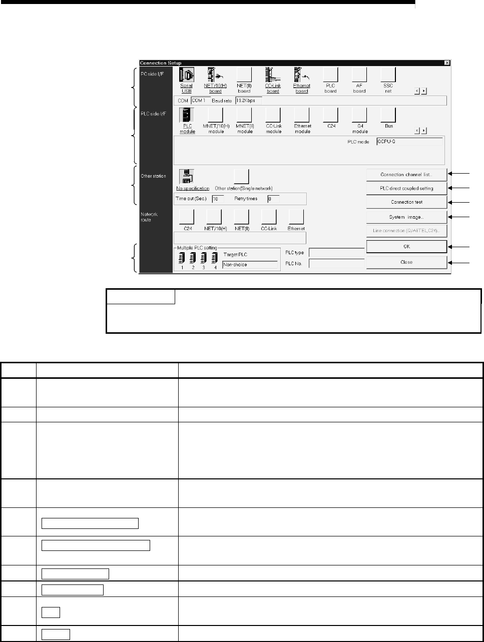
(2) Making the target setup
3)
1)
2)
4)
5)
6)
9)
10)
7)
8)
POINT
A yellow icon indicates that it has already been selected.
For details of Target setup, refer to the GX Developer Operating Manual.
No. Item Description
1) PC side I/F
Choose the personal computer side interface.
Double-clicking enables detail setting.
2) PLC side I/F Choose the connected PLC side module.
3) Other station
Automatically selected according to the PC side I/F setting. (Need not be
selected)
Double-clicking enables the setting of the communication time check period
and retry count.
4) Multiple PLC setting
You can specify any of No. 1 to No. 4 when the connection station is the
QCPU (Q mode) in a multiple PLC configuration.
5)
Connection channel list
button
Used to return the settings to the initial settings.
(The initial settings are "RS-232C", "PLC module" and "No specification".)
6)
PLC direct coupled setting
button
Used to display a list of selectable connection target paths and choose the
target path.
7)
Connection test
button
Used to conduct a test for communication with the connection station.
8)
System image
button
Used to display the selected connection target path by illustration.
9)
OK
button
Used to determine the target setup.
After determination, a connection station check is made automatically.
10)
Close
button
Used to cancel the settings and close the screen.


