


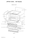
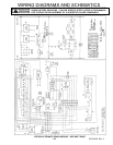
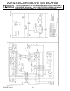
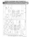
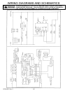
UPPER OVEN - RST Models
105 RC231002 Rev. 3
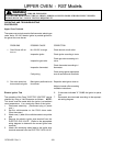
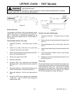
Oven Door Alignment
Loosen (do not remove) the three (3) screws holding the top
hinge to the chassis. Move the hinge to the right to raise the
left side of the door, or to the left to lower the left side of the
door.
Splash Plate Trim/Splash Plate Glass
Remove the three (3) screws securing splash plate trim to
underside of upper oven. Support splashplate glass then
remove trim and glass.
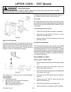
Jacket End
Removal - Remove the side brace trim. Remove the screw
at the bottom front corner of the jacket end. Remove the
upper oven door if the right jacket end is to be removed; or,
the control panel if the left jacket end has to be removed.
Drill out the three (3) pop rivets on the front flange of the
jacket end and the five (5) pop rivets on the black flange of
the jacket end. Lift the jacket end off the oven chassis.
NOTE: When installing the jacket end, the front flange must
be pop riveted in place. However, #8 x 3/8" self-tapping
screws can be used on the rear flange if desired.
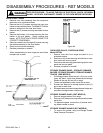
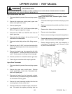
Decorative Panel
Removal - Remove the five (5) screws along the bottom
edge of the air intake panel below the upper oven. Remove
the screw at each end of the front of the air intake panel. Pull
the panel forward.
Disassembly - Disconnect the wires from the switches on
the air intake panel from the range. Depress clips securing
the switch assemblies to the air intake panel, remove
switches from the air intake panel.
Main End Panel
1. Remove maintop to avoid possible damage. Remove
filter filler strip and splash plate. Remove the side
brace trim rail.
2. Remove screw holding trim rail at bottom front corner
of range. Remove all screws holding backplate and
end panel on the side being removed.
3. Remove the inside side brace (below upper oven) by
moving the front edge of the side brace toward the
center of the range and sliding forward at the same
time.
4. Slide the trim rail forward and off the range.
5. Remove the end panel.
6. Reverse the procedure to install.
Light Socket
Upper Oven - Remove upper terminal block from range
terminal block (behind splash plate). Remove control panel.
Disconnect light socket wires from the wire nuts. Remove
oven lamp. Press on both sides of the black clip holding the
socket to the housing and push socket into oven compart-
ment.
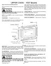
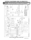
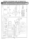
Fluorescent Light System
The fluorescent light system uses a starter and a ballast
which are used in conjunction with the fluorescent lamp. To
test the fluorescent lamp, push in on the switch. The lamp
should light and should remain lit. If it does not light and
remain lit, check the wiring using the diagram in the appro-
priate portion of this service manual. Replace by process of
elimination to locate any faulty parts.
Fluorescent Lamp
Remove filter filler strip from range (at top of splash plate
below upper oven). Lower splash plate. Lift lamp straight
up out of lampholders. DO NOT TURN LAMP!
Lampholder
Remove filter filler strip and splash plate. Disconnect upper
terminal block from range terminal block. Remove wires
leading to the nearest wire nuts from the lampholders.
Remove the two (2) screws holding each lampholder in
place.
Ballast
Remove filter filler strip and splash plate. Disconnect upper
terminal block from range terminal block. Remove wires of
ballast from nearest wire nuts. Remove two (2) nuts
mounting ballast.
Light Switch and Fluorescent Light Switch
Remove air intake grille (below upper oven door). Press
Tinnerman spring on switch assembly against end of switch
and remove switch from opening. Disconnect switch wires.