


FIRE OR EXPLOSION - TO AVOID THE RISK OF ELECTRICAL SHOCK, PERSONAL
INJURY, OR DEATH, DISCONNECT POWER TO THE OVEN BEFORE SERVICING.
DISASSEMBLY PROCEDURES - RST MODELS
91 RC231002 Rev. 3
CLOCK DISPLAY BOARD REMOVAL
Slide In Models
1. Shut off power to the range.
2. Partially remove the control panel. Follow Control
Panel Removal Procedures, Steps 2 - 5.
3. Remove the six (6) clock control buttons by pulling
them out of the clock display board.
4. Remove the left rear and right rear top burner knobs.
5. Remove the two (2) screws that secure the clock
display board mounting bracket to the control panel.
6. Disconnect the wire harness connector plug from the
back of the display board and remove the display
board and mounting bracket assembly.
7. Lift the clock glass out of the mounting bracket.
8. Remove the four (4) clock display board mounting
screws and remove the board from the bracket.
9. Follow reverse procedures to install the clock display
board.
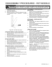
TOP BURNER ACTUATOR SWITCH
1. Disconnect electricity at main disconnect plug.
2. Remove top burner knobs.
3. Remove screw under control panel and remove screws
securing control panel end caps on top left and right
sides. Pull control panel towards you then lift up on
control panel to clear top burner valve stems.
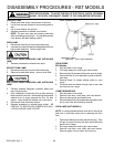
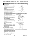
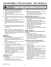
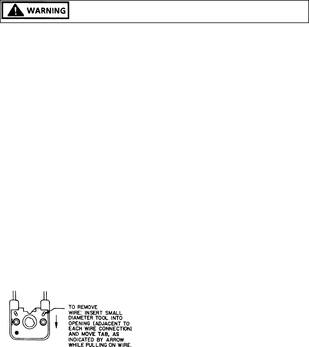
4. Depress tab inside top burner actuating switch (small
oblong hole - one (1) for each wire). To remove wire,
see Figure Below.
5. Lift top burner actuating switch off top burner valve.
NOTE: Bared wires are pushed into position and are
self locking inside switch. Best results are obtained
by baring a fresh strip of wire into switch.
6. Reverse procedure to reinstall switch. Switch must
be seated properly on valve. Switch "snaps" onto
valve stem.
Figure 85 - Top Burner Switch
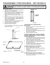
TOP BURNER VALVE
1. Disconnect electricity at main disconnect plug.
2. TURN OFF GAS SUPPLY TO RANGE.
3. Remove main top and control panel.
4. Lift off top burner actuating switch from top burner
valve to be replaced.
5. On models without sealed burners, remove top burner
to valve being replaced. On models with sealed
burners, disconnect tubing from valve to venturi at
valve, or remove top burner assembly.
6. Using a 1/4" nut driver - remove nut securing top
burner valve to manifold.
7. Reverse procedure to reinstall top burner valve. BE
CERTAIN TO CHECK TOP BURNER VALVE FOR
GAS LEAK WITH LEAK DETECTOR OR WARM
SOAPY WATER.
MANIFOLD
1. Shut off power to the range. Shut off gas supply to the
range.
2. Remove grates, burner bowls, and main top.
3. Partially remove control panel. Follow Control Panel
Disassembly Procedure, Steps 3 - 5.
4. Remove one (1) screw to each top burner valve and
remove valve from manifold.
5. Disconnect feed tube to manifold. On sealed burner
units there are two (2) feed tubes which must be
disconnected.
6. Remove two (2) screws securing manifold to front
frame.
When replacing manifold, remove feed tube fitting (s)
and reinstall fitting with new sealer in replacement
manifold.
BE CERTAIN TO CHECK MANIFOLD, BURNER
VALVE, AND FEED TUBE(S) CONNECTIONS FOR
GAS LEAKS WITH LEAK DETECTOR OR SOAP
SOLUTION.