


INSTALLATION INSTRUCTIONS
19 RC231002 Rev. 3
minutes, no longer. Be sure the liquid completely covers
the cap and base portion of the assembly. After 20
minutes, remove burner, cool slightly and rinse thoroughly
with cold water. Be sure hands are protected to prevent
burns from hot water. Be sure all the solution is completely
rinsed off both the inside and outside of the burner. If some
stains still remain, rub with a "Dobie" pad.
The burner may then be left to dry at room temperature or
be placed in the oven at 170° for 1/2 hour. BE SURE TO
PROTECT YOUR HANDS WHEN REMOVING DRIED
BURNERS FORM THE OVEN.
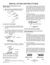
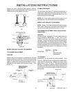
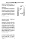
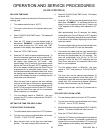
UNIVERSAL GAS ORIFICES
With the exception of the Broiler Burner and Sealed Top
Burner, orifices for these models are of the coaxial type.
They contain a double coaxial orifice hood and universal
pin. The hood orifice is sized for Natural Gas (6 inches
water column pressure). The pin orifice is sized for LP Gas
(11 inches water column pressure).
The orifice is adjusted for Natural gas as shipped from the
factory. It must be adjusted for use on LP gas. This
requires that the orifice hood be screwed or turned down
approximately two (2) turns onto the pin. The hood should
be turned down snug but not tight to the point where it
damages or distorts the pin. (See Figure 19.)
When set up for Natural Gas, gas flows around the pin and
through the orifice of the hood which is sized for Natural
Gas. When the hood is screwed down for LP gas, the gas
flow is only through the hollow pin which is sized for LP gas.
Figure 30 - Universal Orifice
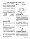
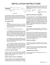
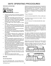
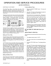
OVEN THERMOSTAT KNOB ADJUSTMENT
Models without electronic Range Control (ERC)
Cooking recipes are written to take into consideration that
oven thermostats have manufacturing tolerances, and
may not provide an average temperature exactly on the
thermostat setting. If the temperature average reading is
beyond the ±25° tolerance range, a limited adjustment can
be made with the adjustable skirt on the knob. The
adjusting screw on the thermostat is sealed and no adjust-
ment can or should be attempted. The rear of the adjust-
able skirt shown here is self-explanatory.
Figure 31
NOTE: These thermostats (Robertshaw) have a cement
coating over the adjusting screw. Evidence of attempts to
adjust these thermostat nullifies the warranty.
For Thermostat Calibration on models with the Elec-
tronic Range Control (ERC), see section on ERC
Operating and Testing Procedures.
When making any temperature adjustments, a reliable test
instrument should be used to accurately determine the
oven temperature.
A reliable test instrument of the thermocouple type is
preferred which will allow temperature readings with the
door closed.
Position the thermocouple clip of the test instrument on the
center of the oven rack that is positioned in the center of the
oven cavity. The thermocouple of the test instrument
should be "weighted" or "loaded" in order to represent more
closely the average cooking temperature of the oven
versus the on-off cycling of the thermostat with the full rate
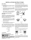
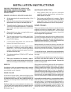
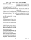
gas valve. The procedure for loading a thermocouple is
illustrated in Figure 20.
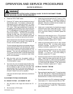
Figure 32 - "Loading" A Thermocouple
An 8 1/2 x 11-inch piece of aluminum foil should be folded
five (5) times, doubling the thickness with each fold. After
the fifth fold, place the thermocouple in the center of the
aluminum piece as shown and fold once more. Finally, fold
the sides so the foil clings to the thermocouple. The loaded
thermocouple will then provide temperature readings on
the thermometer that more closely resemble the mean or
average temperature of the oven as it cycles on and off
above and below the temperature setting.
With all the controls properly set for "Bake", turn the oven
thermostat to 350°.