


OPERATION AND SERVICE PROCEDURES
Electronic Range Control (ERC) (Models w/Two Piece Control)
RC231002 Rev. 3 38
TO AVOID THE RISK OF ELECTRIC SHOCK, PERSONAL INJURY OR DEATH DISCONNECT POWER
BEFORE SERVICING, UNLESS TESTING REQUIRES IT.
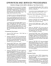
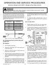
If a higher resistance is indicated disconnect the intercon-
nect harness from the sensor and recheck the sensor
resistance to assure that the problem is in the sensor and
not in the interconnect harness or due to a bad connection.
The following table shows the corresponding resistance for
different oven temperatures.
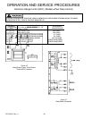
SENSING ELEMENT
TEMPERTURE
SENSING
RESISTANCE
75°F 1091 ± 5.5 OHMS
350°F 1654 ± 11 OHMS
535°F 2018 ± 16 OHMS
875°F 2652 ± 24 OHMS
Figure 38 - E.R.C. Oven Temperature Sensor
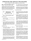
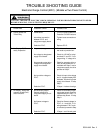
ERC TROUBLESHOOTING FAILURE CODES AND
CALIBRATION
ERC REMOVAL
1. Shut off power to the range.
2. Remove the "TIME/TEMP. SET" knob by pulling it off
of the control shaft.
3. Remove the eight (8) function control buttons by
pulling them out of the ERC.
4. Remove the two (2) control panel lower trim mounting
screws. Carefully pull the lower trim and control panel
glass towards the front of the range and remove trim
and glass.
5. Remove the four (4) backguard control panel mount-
ing screws (two (2) each side) and pull the panel
assembly forward. The ERC input and relay drive
voltages can now be tested at the ERC J1 connector
with power applied to the range. (See ERC voltage
tests and Figure 37.) The sensor resistance can also
be checked by removing the J2 connector and insert-
ing the ohmmeter leads into the connector plug
terminals.
6. To remove the ERC, disconnect the J1 and J2
connectors and remove the four (4) ERC mounting
screws.
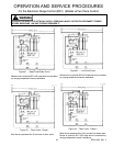
ERC VOLTAGE TESTS
1. Partially remove the ERC from the control panel.
Follow the ERC Removal Procedures, Steps 1 - 5.
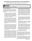
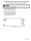
2. To check the input voltage for the vacuum fluorescent
display, insert the AC voltmeter leads into the J1
connector at pins J1-1 and J1-2, and turn on power to
the range.
Figure 25 - Electronic Range Control Pin Identification
A voltage reading of approximately 3.2 VAC should
be indicated. If no voltage is indicated, check for
loose connections, open wire (s) and relay/power
supply circuit board output voltage at pins J1-7 and
J1-8 on the relay board.
3. To check the input voltage that the ERC uses to drive
the bake/broil relays, insert your AC voltmeter leads
into the J1 connector pins J1-3 and J1-4. A voltage
reading of approximately 20.3 VAC should be indi-
cated. If no voltage or a low voltage is indicated,
check for the input supply voltage at pins J1-3 and J1-
4 (Step 3).
4. To check the bake relay drive voltage, insert your DC
voltmeter leads into the J1 connector at pins J1-9 and
J1-5, and program the ERC for a bake operation.