OPERATION AND SERVICE PROCEDURES
RC231002 Rev. 3 72
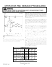
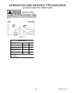
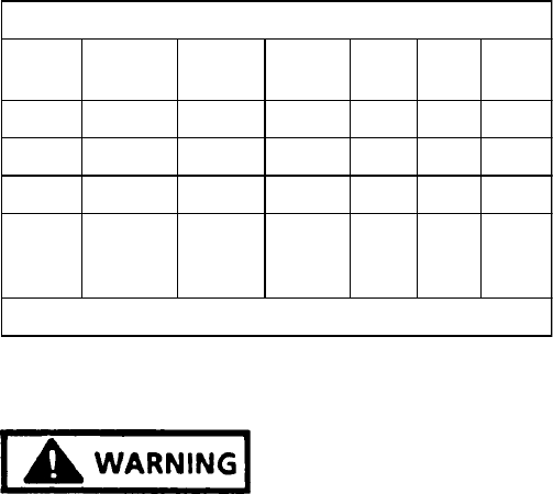
ohms range and following the thermostat contact chart.
Power to the oven must be turned off and the thermostat
wiring removed when checking the contacts for continuity.
Access to the thermostat contacts can be made by remov-
ing the control panel.
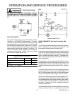
THERMOSTAT (T’STAT)
KNOB
1-2
COM.
N.O.
COM.
N.C.
C-BR C-BA 7-9
OFF
N.S. N.S. N.S. O O O
BAKE
CYCLES N.S N.S O X O
BROIL
CYCLES N.S N.S. X O O
CLEAN
CYCLES
X
BELOW
700°F
X
ABOVE
700°F
O O X
O = OPEN X = CLOSED N.S. = NOT SPECIFIED
Thermostat Contact Chart
FIRE OR EXPLOSION
TO AVOID THE RISK OF ELECTRICAL SHOCK,
PERSONAL INJURY OR DEATH DISCONNECT POWER
BEFORE SERVICING, UNLESS TESTING REQUIRES
IT.
SPARK MODULE TESTING
When properly operating, the spark module will produce a
spark at the ignitor accompanied by a sharp snapping
sound each time the ignitor sparks.
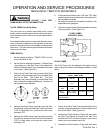
The spark module is located under the burner box on the
left side.
The sealed top burner units have two (2) spark modules,
one (1) on the left and one (1) on the right or one (1) spark
module with four (4) ignitor connections.
TO CHECK THE MODULE
1. Disconnect electricity at disconnecting plug, and turn
off gas supply to the range.
2. Check wiring against wiring diagram to be sure all
terminals and wire-connections are correct and tight.
3. SET VOLT/OHMMETER ON THE 120 VAC SCALE
or higher.
4. Attach one (1) meter lead to the "L" wire terminal on
the spark module.
5. Attach the remaining lead of the test meter to the "N"
"WHITE" terminal on the spark module.
6. Reconnect electricity at main disconnect plug.
7. Turn all top burner knobs to the "LIGHT" positions.
8. No line voltage (115 VAC ± 10 VAC) at test meter
indicates the electrical circuit is interrupted before
spark module.
9. Line voltage at test meter - check ignitors.
10. If ignitors are OK; then replace ignition module.
TOP BURNER SPARK IGNITORS
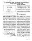
A spark ignitor is located between each pair of left and right
burners. Sealed burner units have an electrode for each
burner. When any of the burner valves is turned to the
"LITE" position, the spark switch on the valve closes,
supplying 120 VAC to the spark module. This activates the
module which produces the spark at the ignitor electrode
to light the burner.
TO CHECK THE SPARK IGNITORS
1. Disconnect electricity at main disconnect plug.
2. Disconnect the high voltage spark ignitor leads from
the terminals on the spark module.
3. SET THE VOLT/OHMMETER ON THE "RX1" OHM
SCALE (adjust zero).
4. Attach one meter lead to a good ground (bare metal)
on the range body.
5. Touch the remaining meter lead to the terminal of the
ignitor lead. A continuity reading from the ignitor lead
indicates the ignitor lead is shorted to ground. If no
continuity reading from the ignitor lead to ground,
proceed to Step 6.
6. Attach one (1) meter lead to the terminal of the ignitor
lead and touch the remaining meter lead on the
opposite end of the ignitor lead which is attached to
the top burner mounting bracket. Repeat same
procedure with the other ignitor lead. No continuity on
the lead indicates an open circuit in the ignitor lead
wire. (On sealed burner units, one (1) meter lead
must be attached to the electrode socket at the
venturi.)
SPARK SWITCH TEST
Each spark switch is connected in parallel in the spark


