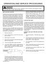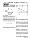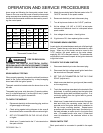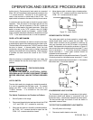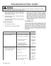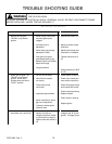
TROUBLE SHOOTING GUIDE
FIRE OR EXPLOSION
TO AVOID THE RISK OF ELECTRICAL SHOCK, PERSONAL INJURY OR DEATH DISCONNECT POWER
BEFORE SERVICING, UNLESS TESTING REQUIRES IT.
RC231002 Rev. 3 78
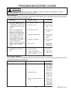
PROBLEMS POSSIBLE CAUSE CORRECTION
1. Burners will not ignite.
"SPARK" at top burner
ignitors.
A.
B.
C.
D.
E.
Burner venturi, burner cap
or burner ignition ports
clogged.
Air shutters out of
adjustment.
Burner flame not correctly
adjusted (LP GAS)
Poor ground on ignitor
grounding bracket or gap
between ignitor and bracket
dimple is too large.
Low gas pressure
A.
B.
C.
D.
E.
Clean burner venturi, or i
Adjust air shutter accord
instruction.
Adjust burner flame acc
o
information in installation
Tighten bracket and /or
0").
Check pressure (6" WC
P
for LP).
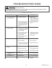
2. Burner will not ignite. No
"SPARK" at top burner
ignitors. Burner knob
pushed down and held in
"LIGHT" position.
A.
B.
C.
D.
E.
F.
No 120 VAC to range.
Micro Switch contacts
not closing.
Faulty wiring or bad
connection.
Inoperative spark module.
Ignitor ceramic dirty, spark
gap out of adjustment.
Cracked or broken ignitor
extension lead.
A.
B.
C.
D.
E.
F.
Check electric at wall o
u
Check micro switch posi
micro switch contacts (
S
Check wiring against ap
p
all terminals and conne
c
Check module accordin
g
Replace module.
Clean ceramic, check g
r
Replace ignitor.
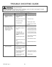
3. An intermittent or occasional
spark after unit is turned off.
A. Crossed polarity. When
polarity is correct, no
voltage is present at neutral
to ground and no voltge to
spark module with switch at
off.
A. With all switches in the
"
voltage at the "N" termi
n
ground. If voltage is pre
s
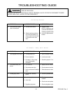
Non-Sealed Top Burners


