


OPERATION AND SERVICE PROCEDURES
(SLIDE IN MODELS)
RC231002 Rev. 3 28
set to read 120 VAC or higher, attach the meter leads
to the L1 and N wire leads and turn on power to the
range. A voltage reading of approximately 120 VAC
should be indicated. If no voltage is indicated, check
the range wiring. If 120 VAC is indicated shut off
power to the range and reconnect L1 and N wire leads
to the P.C. board terminals.
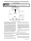
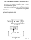
2. Disconnect the 20 pin ribbon cable connector from
the P.C. board J2 connector and turn on the power to
the range. Check for voltages at the following pins at
the J2 connector. (See Figure 28.)
PINS VOLTAGE
2-18 -25 to -35 VDC
6-18 -7 to -9 VDC
8-18 -7 to -9 VDC
10-18 -7 to -9 VDC
14-18 -25 to -35 VDC
15-18 -25 to -35 VDC
2-14 2.0 to 3.6 VDC
DISPLAY BOARD TESTING
Shut off power to the range and remove the display board
from the control panel (refer to Disassembly Procedures).
The function switches and diodes on the display board can
be checked at the J1 connector. Install the clock control
buttons into the display board switch housings. Refer to
Figure 30 for the correct pin number identification.
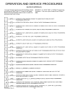
1. To check the "MINUTE TIMER" switch and CR3
diode, connect an ohmmeter (set to RX10 or higher)
to pins 8 and 17 at the display board J1 connector and
press the minute timer button. Reverse the ohmme-
ter leads and again press the "MINUTE TIMER"
button. On reading should indicate infinite ohms and
the other reading should indicate low ohms (the diode
conduction resistance and closed minute timer switch).
If a zero (0), low or infinite ohms reading is indicated
with the meter leads connected in both directions, the
display board should be replaced.
2. To check the "COOK/CLEAN TIME" switch and the
CR5 diode, connect the ohmmeter leads to pins 10
and 16 at the display board J1 connector and press
the "COOK/CLEAN TIME" button. Reverse the meter
leads and again press the "COOK/CLEAN TIME"
button. One reading should indicate infinite ohms
and the other reading should indicate low ohms (the
diode conduction resistance and closed "COOK/
CLEAN TIME" switch). If a zero, low, or infinite ohms
reading is indicated with the meter leads connected in
both directions, the display board should be replaced.
3. To check the "STOP TIME" switch and the CR5
diode, connect the ohmmeter leads to Pins 6 and 16
at the display board J1 connector and press the
"STOP TIME" button. Reverse the meter leads and
again press the "STOP TIME" button. One (1)
reading should indicate infinite ohms and the other
reading should indicate low ohms (the diode conduc-
tion resistance and closed STOP TIME switch). If a
zero (0), low or infinite ohms reading is indicated with
the meter leads connected in both directions, the
display board should be replaced.
4. To check the "UP" switch and the CR4 diode, connect
the ohmmeter leads to Pins 8 and 20 at the display
board J1 connector and press the "UP" button. Re-
verse the meter leads and again press the "UP"
button. One reading should indicate infinite ohms
and the other reading should indicate low ohms (the
diode conduction resistance and closed "UP" switch).
If a zero (0), low, or infinite ohms reading is indicated
with the meter leads connected in both directions, the
display board should be replaced.
5. To check the "DOWN" switch and the CR4 diode,
connect the ohmmeter leads to Pins 6 and 20 at the
display board J1 connector and press the "DOWN"
button. Reverse the meter leads and again press the
"DOWN" button. One reading should indicate infinite
ohms and the other reading should indicate low ohms
(the diode conduction resistance and closed "DOWN"
switch). If a zero (0), low, or infinite ohms reading is
indicated with the meter leads connected in both
directions, the display board should be replaced.
6. To check the "CLOCK/CANCEL" switch and the CR2
and CR4 diodes, connect the ohmmeter leads to Pins
10 and 20 at the display board J1 connector and press
the "CLOCK/CANCEL" button. Reverse the meter
leads and again press the "CLOCK/CANCEL" button.
One reading should indicate infinite ohms and the
other reading should indicate low ohms (CR2 and
CR4 diode conduction resistance and closed "CLOCK/
CANCEL" switch). If a zero (0), low, or infinite ohms
reading is indicated with meter leads connected in
both directions, the display board should be replaced.
7. The CR1 diode can be checked by connecting the
TO AVOID THE RISK OF ELECTRIC SHOCK, PERSONAL INJURY OR DEATH DISCONNECT POWER
BEFORE SERVICING, UNLESS TESTING REQUIRES IT.