


Controls and Indicators HotCup Operators’ Guide
6740001 10 November, 2007
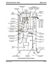
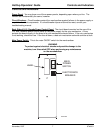
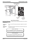
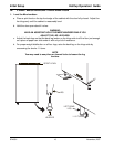
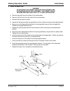
MAIN CONTROLLER DISPLAY
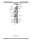
Main Controller PCB Display
. This display consists of two light emitting diodes (LED) mounted on
the controller PCB.
POWER ON
(LED 1)
When lit, this red LED indicates electrical power is applied to the controller
PCB.
HEARTBEAT
(LED 2)
When flashing, this red LED indicates that the controller PCB is active, and
the software is operating.
LED1LED2
MAIN CONTROLLER
PCB ASSEMBLY
POWER ON
(LED 1)
FLASHING
HEARTBEA
T
(LED 2)
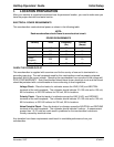
NORMAL CONDITIONS:
When the merchandiser is operating normally, you should see a
steady red POWER ON indicator. The red HEARTBEAT indicator
ERROR CONDITIONS:
If an error is present, the red HEARTBEAT indicator will flash
with an unbalanced on/off pattern (on longer than it is off). The