21
3.9 Motor and Heater Plate Locknuts
There are two locknuts holding the heater plate and motor housing assembly into the base of the tub, these
form a watertight seal by compressing the two seals.
When reassembling the motor, it is important that a motor shim is placed between the inner locknut and the
inner element seal.
The outer locknut has locations that hold the drain hose, ll hose and wiring loom in place.
3.10 Drain Cycle
The drain pump is a self-priming centrifugal pump that only pumps when the motor is rotating in the drain
direction (anti-clockwise). It has a ve bladed impellor pushed into a spline on the lower end of the rotor shaft.
The drain pump housing, which incorporates an inlet and outlet pipe, is welded to the motor housing, hence
captivating the motor.
The inlet pipe plugs straight into the drain sump in the tub and is sealed there by a small ‘O’ ring.
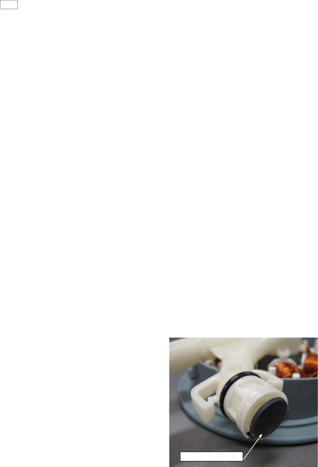
The outlet pipe has a non-return ap valve to prevent soiled water returning to the tub.
The drain hose is an extruded blow moulded hose that is routed over the link assembly and exits out of the base
of the product and is connected to a domestic drain.
The pump speed during the drain cycle is approx. 4200 rpm. In hardware output diagnostics test mode it is set
to the same speed to aid diagnosing drain problems.
On a double product, the drain motor on the tub which is not being used will run for a short time during the
nal drain phase of a wash cycle. This is to remove any drain water that may have back owed in to the unused
tub.
This concurrent drain will not happen if the unused tub is open. If the user presses the power button after
water has been placed in the tub, the product will initiate a “power o” drain and empty the tub.
Non Return Valve


