


57
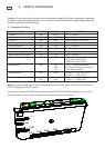
9 SERVICE PROCEDURES
Caution: Due to the use of electronic switch mode power supply, all internal components, regardless
of supply voltage, should be treated as live to earth (i.e. equal to the mains supply voltage) when the
power is supplied to the DishDrawer.
9.1 Component Testing
DEVICE CONNECTOR PIN PAIR DESCRIPTION
Fill Valve P205 10 & 11 65 +/- 10 Ohms
Lid Motor P205 6 & 7 check if open or short circuit
Lid Motor P205 8 & 9 check if open or short circuit
Rinse aid pump P204 1 & 2 65 +/- 10 Ohms
Detergent diverter P204 3 & 4 65 +/- 10 Ohms
Fan P203 1 & 2 check if open or short circuit
Water softener bypass valve P202 1 & 2 65 +/- 10 Ohms
Water softener brine pump P202 3 & 4 65 +/- 10 Ohms
Temperature sensor P101 1 & 2 12000 Ohms @ 20
o
C (68
o
F)
8300 Ohms @ 30
o
C (86
o
F)
3000 Ohms @ 60
o
C (140
o
F)
Motor phases P201 1 & 2
2 & 3
1 & 3
8.0 +/- 5 ohms (per winding)
16 Ohms phase to phase from the
controller connection.
Dropper resistor P101 4 & 5 98 ohm +/- 7 (NZ, AU, EU, UK)
24 ohm +/- 3 (US, CA, TW)
Element P101 & Power
Plug
6 & neutral on
plug
50 ohm +/- 4 (NZ, AU, EU, UK)
24 ohm +/- 3 (US,CA,TW)
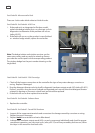
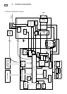
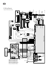
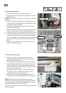
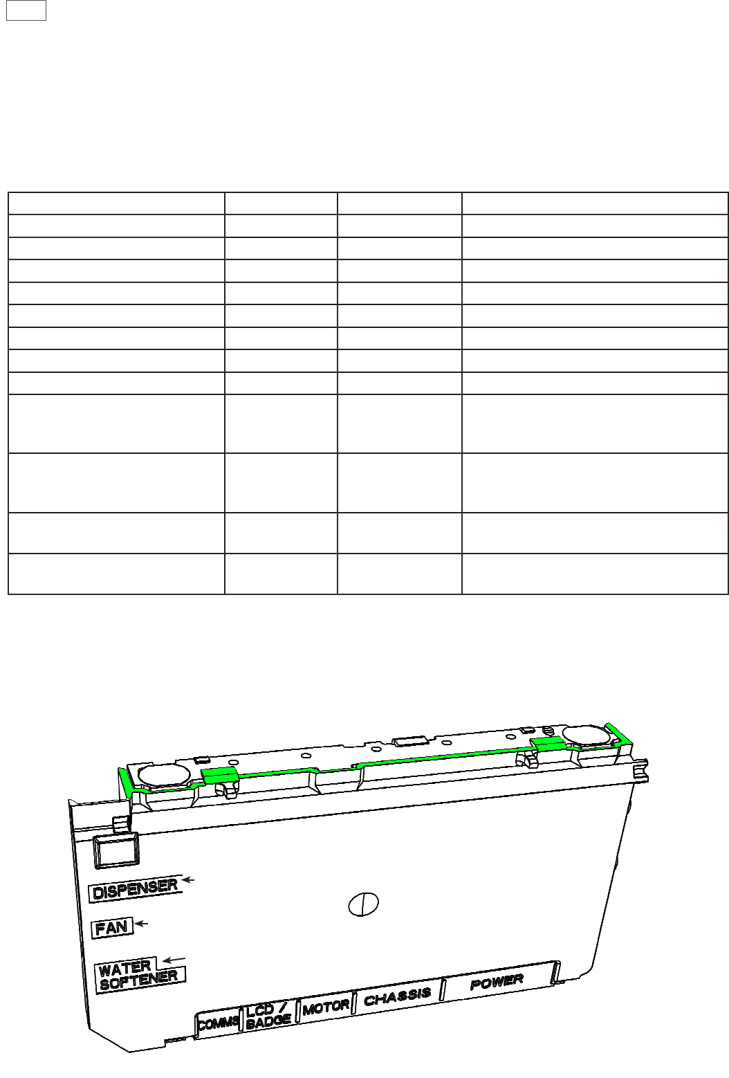
Note: Pins are counted right to left on connector harnesses P101 Power, P205 Chassis, P201 Motor,
P303 LCD/Badge and P302 Comms.
Connectors on harnesses P202 water softener (if tted), P203 Fan & P204 Dispenser, pin 1 is at the
bottom of the connector, refer to illustration below for harness connections.
P201
P205
P101
P303
P204
P203
P202
P302