


13
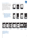
MODEL OPTIONS
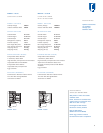
Model I601R
914 mm
All Refrigerator
Model I601RG
914 mm
All Refrigerator
with Glass Door
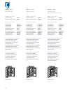
Model I601F
914 mm
All Freezer
Model I611
762 mm
Over-and-Under
Model I611G
762 mm
Over-and-Under
with Glass Door
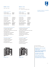
Model I650
914 mm
Over-and-Under
Model I650G
914 mm
Over-and-Under
with Glass Door
Model I661
914 mm
Side-by-Side
Model I642
1067 mm
Side-by-Side
Model I685
1067 mm
Side-by-Side
Ice | Water Dispensing
Model I632
1219 mm
Side-by-Side
Model I695
1219 mm
Side-by-Side
Ice | Water Dispensing
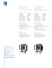
Model ICB648PRO
1219 mm
Side-by-Side
Built-In or Free-Standing
Model ICB648PROG
1219 mm
Side-by-Side
with Glass Door
Built-In or Free-Standing
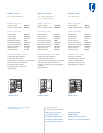
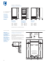
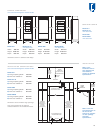
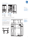
PLANNING INFORMATION
Although the Sub-Zero Built-In line offers a wide
range of designs and configurations, the basic
planning considerations for all models have
much in common. As you integrate Built-In
models into your overall plan, review installation
requirements for your particular model(s). The
Installation Specifications illustrations provide
planning information for all Built-In models—
overlay and stainless steel.
Allow the door(s) to open a minimum of 90˚ or
you‘ll have problems removing drawers. With the
door opening at 90˚, you may have to move
drawers slightly to clear the door interior.
For corner installations, allow for a minimum
76 mm filler so that the door can open to 90˚.
If you‘re using raised panels, consider using a
wider filler.
When units are installed side by side, a filler strip
is recommended. The width of this filler strip will
vary depending on the configuration and panels
you use.
Be sure to add the filler strip width to your
finished rough opening dimension. In any
installation of two units side by side without a
filler strip, add an additional 13 mm to your
combined numbers. This will allow for the
proper width.
IMPORTANT NOTE: Refer to the full-scale illus-
trations at the end of this section for specifics
on door openings and filler size alternatives.
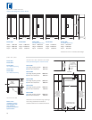
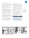
ELECTRICAL REQUIREMENTS
International models from the factory designed
without a transformer require a 220/240 V AC,
50/60 Hz electrical supply, fused at the correct
rating for the unit. If required by local or national
codes, the power cord can be easily replaced
using the power inlet device.
International models using a factory installed
transformer require a 220/240 V AC, 50/60 Hz
electrical supply, fused at the correct rating for
the unit. These models will come equipped with
Schuko power cords. The power cord may need
to be replaced depending on local and national
codes. The USA power cord that is supplied
with the product must be disconnected with the
appropriate transformer output to be connected
in its place.
IMPORTANT NOTE: The electrical outlet must
be grounded. The outlet must be flush with the
back wall. Refer to the Installation Specifications
illustration for your model for exact placement.
IMPORTANT NOTE: A ground fault circuit
interrupter (GFCI) is not recommended and may
cause interruption of operation.
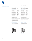
PLUMBING CONSIDERATIONS
For Built-In models with an automatic ice maker,
rough in the water supply line. Connect a
6.35 mm OD copper line to the house supply,
being sure to use an easily accessible shut-off
valve between the supply and the refrigerator.
Do not use self-piercing valves. A saddle valve kit
(4200880) is available from your Sub-Zero dealer.
For Built-In models, a line filter is required when
water conditions have a high sediment content.
The ice maker operates on water pressure of 1.4
bar to 6.9 bar.
IMPORTANT NOTE: In some cases a reverse
osmosis water filter system may not be able to
maintain the minimum water pressure consistently.
IMPORTANT NOTE: A reverse osmosis system
can be used with Models ICB648PRO and
ICB648PROG, provided there is constant water
pressure of 1.4 bar to 8.3 bar supplied to the
unit at all times.
The water line should be routed up through the
floor within 13 mm from the back wall and no
higher than 76 mm off the floor. If you have to
come through the wall, make sure the water line
is no more than 76 mm from the floor.
Regardless of the routing, allow 1 m of excess
copper tubing to remain outside the wall or floor
for easy connection to the unit. Refer to Installa-
tion Specification illustrations.